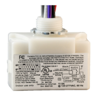
Echoflex Installation Guide
LED Fixture Controller
LED Fixture Controller Page 7 of 8 Echoflex
• In factory default state, when powered up, the Power LED displays
solid red to indicate the controller has no linked devices. To test the
relay(s), press the [Learn] button or link a switch. See relevant switch
documentation.
A maximum of 20 switches or sensors can be linked to one controller.
Blink Codes and Operations
The tables below describe the controller's LED blink codes and operating
activity.
• If the controller is in factory default state, the Power LED remains solid
On.
• If the controller has one or more devices linked to it, the Power LED
repeats a code of blinks that represent the type and number of linked
devices. Long blinks=type. Short blinks=count.
Blink Codes
Description Power LED Learn LED
Factory default On solid Off
Switch(es)
1 long blink followed by
short blinks counting switches
Off
Occupancy
sensor(s)
2 long blinks followed by
short blinks counting sensors
Off
Photo sensor
(max 1)
3 long blinks followed by 1
short blink counting sensor
Off
Central command
4 long blinks followed by
short blinks counting devices
Off
Demand response
5 long blinks followed by
short blinks counting devices
Off

 Loading...