Echoflex Installation Guide
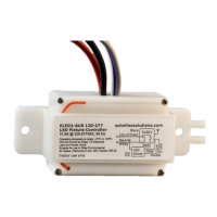
LED Fixture Controller
LED Fixture Controller Page 4 of 8 Echoflex
4. Refer to the wiring diagram to connect the controller to line power,
neutral, and load wires. Use wire nuts on all connections and
individually cap any bare wires, except the orange antenna wire.
5. Ensure the antenna wire is not close to any metal surface (for example:
the lighting fixture metal housing).
6. Connect the gray and the violet wires to the driver or ballast’s dimming
interface (optional).
7. Restore power to the circuit.
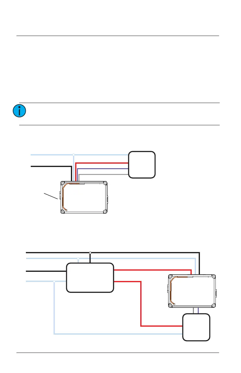
Wiring Diagram
Wiring Diagrams for Emergency Fixtures
Diagram 1 of 2
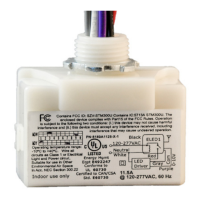
Note:
The Micro USB port is for factory use only. Do not attach
cables or accessories to this port.
Max. Switching Load:
11.5A @ 120-277 VAC, 50/60 Hz
Electronic Ballast or LED Driver
LED Driver
ELED1
Max. Dimming Load: 100 mA sinking
Max. Impulse Voltage: 4000 V
Internal Relay: Type 1.C
Dimming output is Class 1 circuit
Independently Mounted Control for Panel Mount/Surface Mount
Antenna (orange)
Do not cut
or cap
Red - Load, Switched Hot
Violet - Dimming 0-10 V
Gray - Dimming COM
Black - Line, 120-277 VAC
White - Neutral
ELED1
Dimming +Dimming -
LED Driver
LED Driver Hot
LED Driver Neutral
Normal Control Sense
Normal Emergency Load
UL924 Emergency
Bypass Relay
(Echoflex Soluons
EREB-AP)
ELED1 Load Controller
Normal Hot
Normal Neutral
Emergency Hot
Emerency Neutral