EasyManua.ls Logo

ETC Echoflex ELED1-BUN User Manual

ETC Echoflex ELED1-BUN
8 pages
To Next Page IconTo Next Page
Page #1 background imageLoading...
Page #1 background image
Echoflex Installation Guide
LED Fixture Controller
Corporate Headquarters Middleton, WI, USA | Phone +1 608 831 4116
Web echoflexsolutions.com
| Email info@echoflexsolutions.com | Support support.etcconnect.com
© 2021 Echoflex Solutions, Inc. Trademark and patent info: echoflexsolutions.com/ip
Echoflex intends this document to be provided in its entirety. Product information and specifications subject to change.
8189M2100 Rev A Released 2021-03
Overview
The ELED1 Fixture Controller provides wireless control of individual fixture or
single zone lighting based on occupancy state, manual switch action,
ambient light levels, and gateway commands.
This document covers installation of the ELED1 LED Fixture Controller
models. The Echoflex LED Fixture Controller ELED1(H) Configuration Guide
is available for download at echoflexsolutions.com.
The package contents includes the controller, installation guide, and
mounting strap (for ELED1-BUS model).
Prepare for Installation
Echoflex recommends paying special attention to the installation
environment.
High density construction materials and large metal appliances or
fixtures in the space may disrupt wireless reception.
Mount the controller to an electrical junction box or a panel in a
location and at a height where it is not subject to tampering by
unauthorized personnel.
Supplies required to install the controller (not provided):
Appropriately sized wire nuts
Wire insulation
Small cable ties
Two 3/8 inch #8 metal screws (for surface mounting strap only)
Violet
ELED1-BUS
BUS
8189M21
0
0
ELED1-BUN
Question and Answer IconNeed help?

Do you have a question about the ETC Echoflex ELED1-BUN and is the answer not in the manual?

ETC Echoflex ELED1-BUN Specifications

General IconGeneral
BrandETC
ModelEchoflex ELED1-BUN
CategoryController
LanguageEnglish

Summary

Overview of ELED1 Fixture Controller

ELED1 Controller Functionality

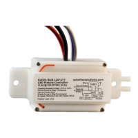
Provides wireless control of individual fixture or single zone lighting based on occupancy, switch action, ambient light, and gateway commands.

Prepare for Installation

Installation Environment and Mounting Advice

Consider construction materials, metal fixtures for reception, and secure mounting location away from tampering.

Required Installation Supplies

Lists necessary items like wire nuts, insulation, cable ties, and mounting screws not included with the controller.

Important Safety Safeguards

Electrical Shock Hazard Warning

Warns of high voltage, requiring qualified installers and adherence to lockout/tag out procedures per NFPA 70E.

Indoor Use and Installation Restriction

Specifies the controller is for indoor use only and must be installed in a junction box or wireway.

Safe Usage and Environmental Conditions

Details environmental limits, mounting height, accessory use, intended application, and servicing qualifications.

Installation Procedures

Adherence to Electrical Codes

Emphasizes following NEC and local electrical code requirements during installation and powering.

Install ELED1 with Nipple

Instructions for mounting the controller directly to a junction box or panel using a nipple.

Install ELED1 with Mounting Strap

Guide for attaching the controller to a fixture or appliance using the provided mounting strap.

Wiring Diagrams

ELED1 Wiring Diagram

Illustrates connections for line, neutral, load, and dimming wires for the ELED1 controller.

Wiring for Emergency Fixtures

Diagram showing ELED1 integration with an emergency bypass relay for fixture control.

Electrical Terminations and Diagrams

Emergency Fixture Wiring Diagram

Diagram 2 of 2 illustrating connections for emergency lighting systems with ELED1.

Controller Wire Specifications

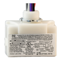
Details connection types, wire colors, and specifications for electrical terminations to the controller.

Controller Interface and Testing

Controller Interface Overview

Describes the LEDs (Power, Learn) and buttons (Clear, Learn) on the controller interface.

Learn and Clear Button Functions

Explains how to use the Learn button for linking devices and the Clear button for resetting states.

Controller Testing Procedure

Guidance on testing the controller's relay functionality in pre-commissioned or factory default states.

LED Blink Codes and Operations

LED Blink Code Descriptions

Details Power and Learn LED blink codes indicating device status, type, and count.

Controller Operating Activity

Describes controller operations like link mode, storing, and clearing link IDs via LEDs.

Compliance and Listings

Regulatory Compliance Information

Provides details on FCC Part 15.231 and IC RSS-210 compliance for the device.

Related product manuals