-8-
E5:Variation due to contact electrode resistance
E7:Variation due to system frequency change
E8:Variation due to system voltage change
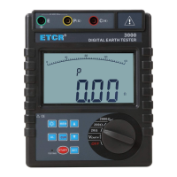
VI. Function Quick Check
FUCTION rotary
switch
Switch on/off ,Function shift, Switch gear
Up/down arrow
button
Data read/numerical value settings
Backlight button Backlight control
START button Start measuring
MODE button
Maximum, Minimum or Average value
mode, Move cursor
CLR button Clear data/Delete data
MEM button Data lock/storage/reading
AL button
Alarm function start/alarm critical value
settings
VII. Operation Methods
1.Switch On/Off
Rotate FUNCTION rotary switch to fulfill switch on and off. When rotary
switch button displays “OFF” for shut-off. The Tester has no auto shut-off
function, so please shut it off after usage in case of battery consumption
saving.
2.Battery Voltage Check
After switch on, if LCD displays low battery voltage icon “ ”,which
indicates that battery voltage is low, and please replace the battery in
compliance with instructions. Adequate battery power can ensure the
accuracy of measurement.
3.Insert and Connection of Rods
Shown as the following figure, stick the auxiliary earth rods P and C into
the ground deeply. They should be aligned at an interval of 5-10m from the
earthed equipment under test. Connect the green wire to the earthed
equipment under test, the yellow wire to the auxiliary earth rod P and the red
wire to rod C from terminals E, P and C of the instrument in order.