-19-
VIII. Measurement Method of Earth Resistance
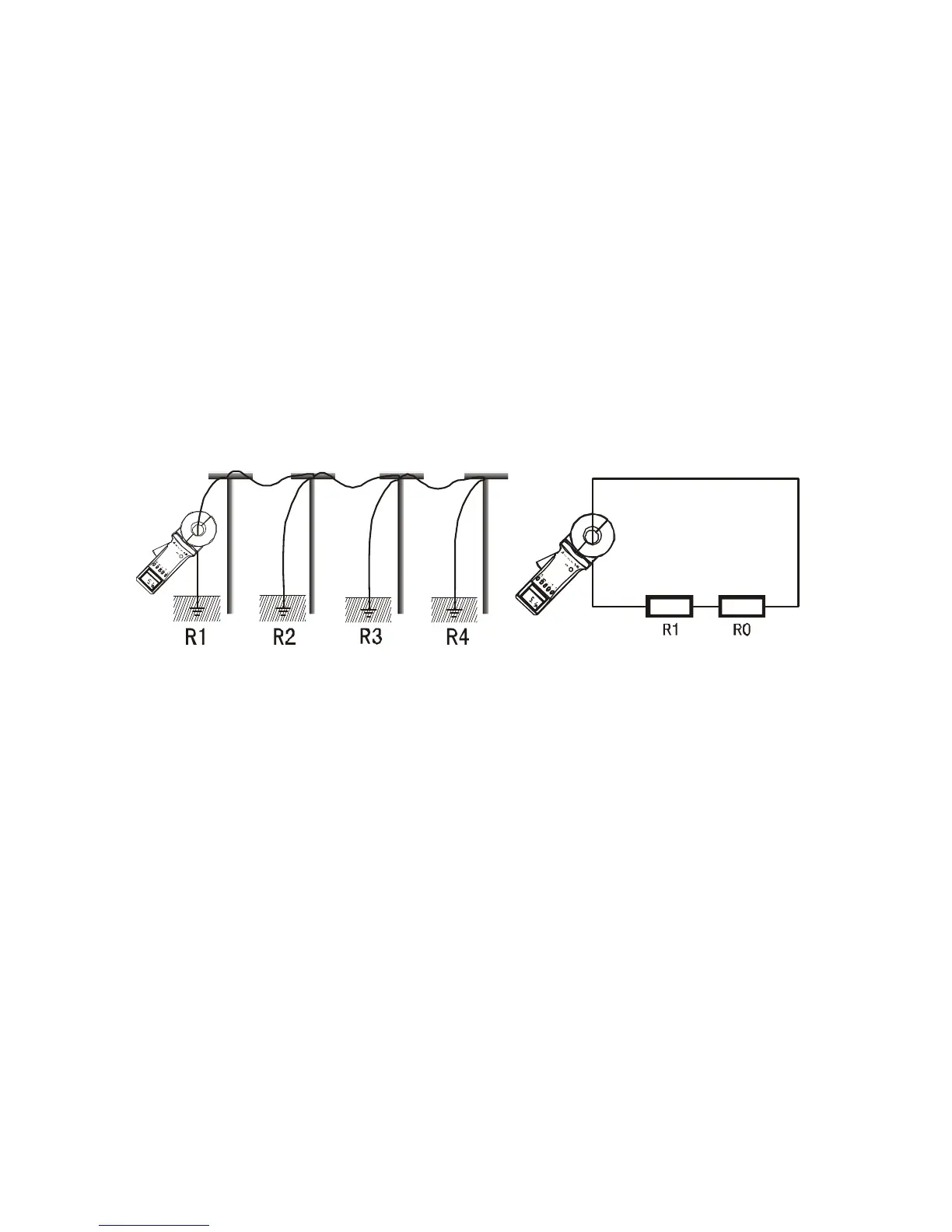
1. Multi-Point Grounding System
As for the multi-point grounding system (such as electricity
transmission tower grounding system, grounding cable
communications systems, certain buildings, etc.), They usually
pass the overhead ground wire (cable shielding layer) connected
to form a grounding system.
As the Meter is in the above measurement, its equivalent electric
circuit is shown in the figure below:
Where: R
1
is the target grounding resistance.
R
0
is the equivalent resistance of the other entire tower
grounding resistances paralleled.
Although strictly on the theoretical grounding, because of the
existence of so-called "mutual resistance”, R
0
is not the usual
parallel value in the sense of electrical engineering (slightly higher
than its IEC parallel output value). But because a tower-grounding
hemisphere was much smaller than the distance between the
towers, and with a great number of locations after all, R
0
is much
smaller than R
1
. Therefore, it can be justified to assume R
0
=0 from
an engineering perspective. In this way, the resistance we