ETEL Doc.- Hardware Manual # DSCDP / Ver G / 6/1/11
DSCDP Hardware Manual 17
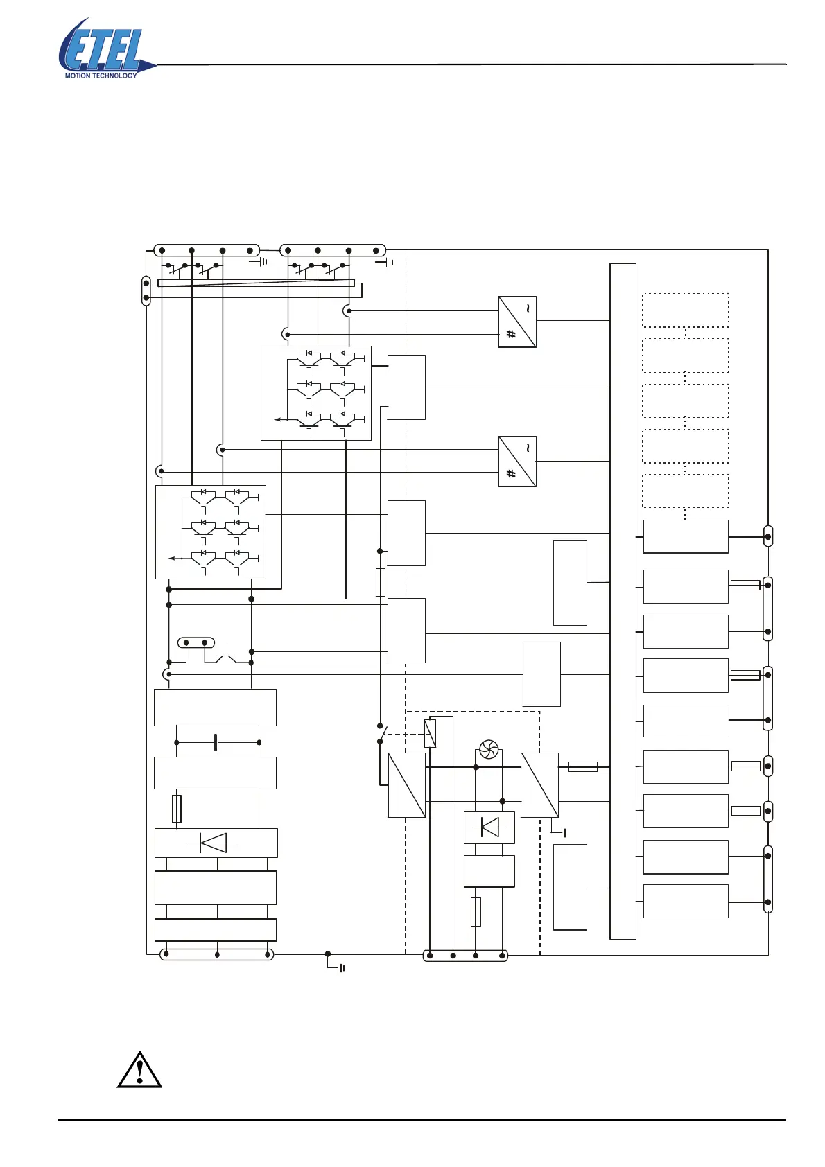
2.2.2 Block schematics
The housed format contains two boards: the servo board and the power supply board. On the servo board, the
power part and the control part are galvanically separated. The inputs and outputs are insulated from the
control part by opto-couplers.
Caution: The GND is internally connected to the DSCDP front panel which is connected to the
ground (PE).
The power GND is not connected to the ground (PE).
ETEL-Bus-Lite2
IN / OUT
TEB
IN / OUT
Digital control
DIP switch
AXIS #
Digital
inputs M1
Digital
outputs M1
Optional
board
Analog(*) / TTL
encoder input M1
Fuse
CAN bus
MACRO bus
PROFIBUS
DSO-HIO
Fuse
JC1 to 3 JC5 JC6 JC9 JC10 JC8
IGBT drive
unit
(POWER)
galvanic
insulation
Current
measure.
PH1 & 3
PH1
PH2
PH3
Thermostat
PE
DC
DC
DC
DC
Fuse
Over / under
voltage
JC7
M
O
T
O
R
O
U
T
P
U
T
Fuse
Fuse
Overcurrent
detection
IGBT power bridge
M1
JC13
+Vaux
GNDaux
P
O
W
E
R
I
N
P
U
T
M
O
V
PH1
PH2
PH3
PE
JC11
IGBT power bridge
M2
M1
M2
IGBT drive
unit
Current
measure.
PH1 & 3
galvanic
insulation
(
CONTROL)
Analog(*) / TTL
encoder input M2
Digital
inputs M2
Digital
outputs M2
Fuse
Fan
L1
L2
L3
PE
Optional short-
circuit relay
+24 VDC
GNDaux
Over
voltage
Fuse
M
O
V
Inrush
limit
Ext.
brake
resistor
≥40Ω
JC14
Filter
JC12
P
OWER
A
U
I
N
P
U
T
STAGE
+
-
X
RELAY
SERVO BOARD
Artisan Technology Group - Quality Instrumentation ... Guaranteed | (888) 88-SOURCE | www.artisantg.com
 Loading...
