ETEL Doc.- Hardware Manual # DSCDP / Ver G / 6/1/11
DSCDP Hardware Manual 27
3.2 Inputs / outputs connectors
3.2.1 Connectors JC9 and JC10: Customer inputs / outputs
Caution: The inputs/outputs cable must be insulated (no contact) from the power and the mains
The inputs and outputs must be connected to an Extra Low Voltage circuit only
(SELV).
The digital inputs and outputs are galvanically insulated from the GND by opto-
couplers.
Caution: These connectors must be handled in an ESD protected environment, only.
Remark: The inputs/outputs cable(s) connected to the DSCDP must be shielded (see §3.7.1
).
The DSCDP has 4 digital inputs (DIN1, DIN2, DIN9 and DIN10) and 2 digital outputs (DOUT1 and DOUT2) per
motor. Every digital input and output is opto-coupled. DIN2 is opto-coupled through a high speed opto-
couplers (100 ns).
Only inputs and outputs interface is considered here. Refer to the corresponding 'Operation & Software
Manual' for more information about the use of these inputs and outputs.
3.2.1.1 Digital inputs
The digital inputs switch to ’1’ when a voltage ranging between +12VDC and +28VDC is applied between pins
DIN+ of the corresponding input and GNDext.
The digital inputs switch to ‘0’ when a zero voltage is applied between pins DIN+ of the corresponding input
and GNDext.
Remark: When using an external ‘positive limit switch’, connect it to DIN10.
When using an external ‘negative limit switch’, connect it to DIN9.
When using an external ‘home switch’, connect it to DIN2.
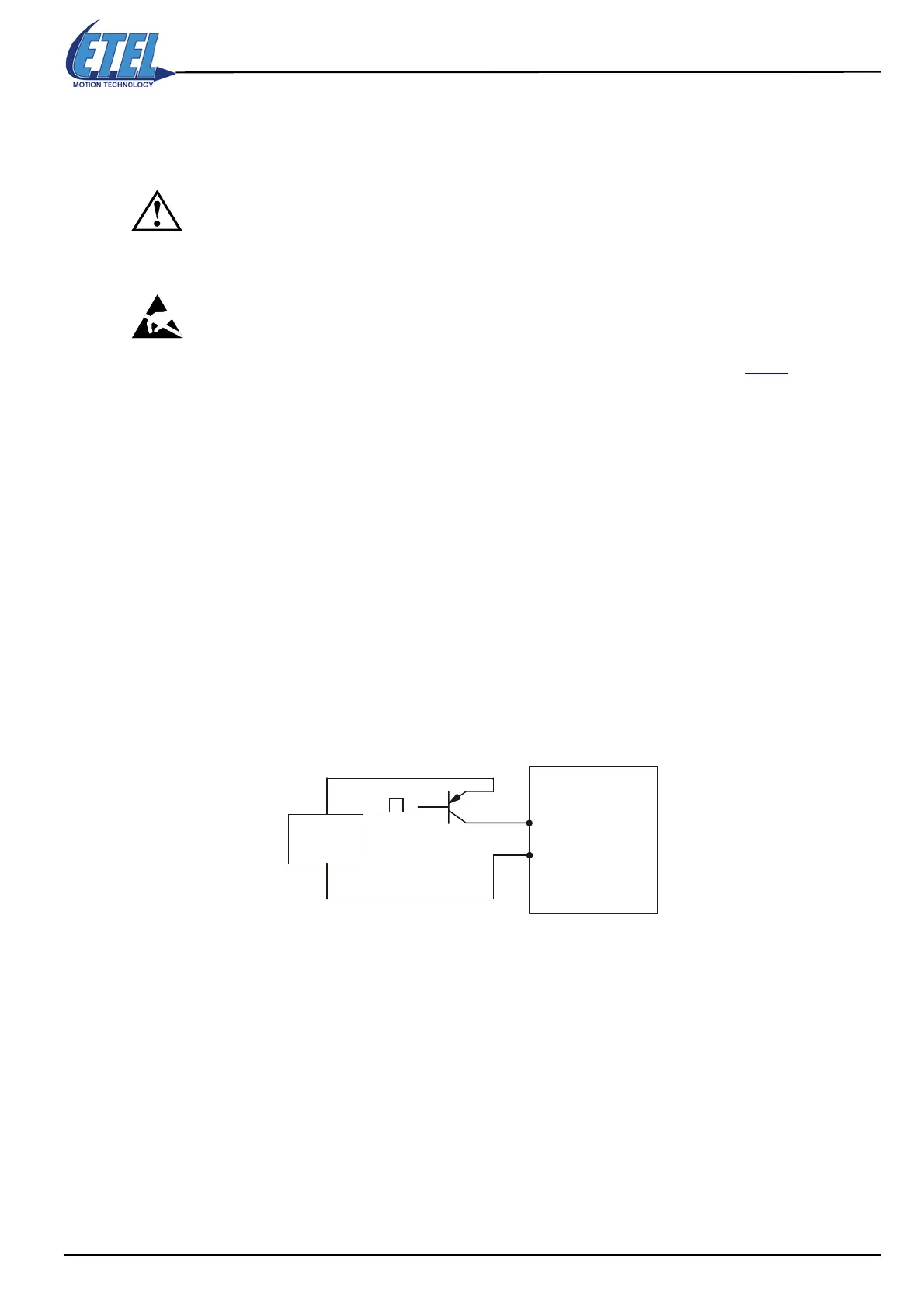
The auxiliary supply can be external to the controller, as shown below:
Digital Hall effect sensor
3 digital inputs (H1+, H2+ and H3+) are used to connect a digital Hall effect sensor. This sensor is used for the
motor commutation thanks to three digital signals (one for each Hall effect sensor). The digital Hall effect
sensor is available with the firmware from version 1.12A. On the following graph, the Hall signals and the sine
voltages between the motor phases are displayed:
External
supply
DSCDP
DIN1 +
GNDext
1
5
Artisan Technology Group - Quality Instrumentation ... Guaranteed | (888) 88-SOURCE | www.artisantg.com
 Loading...
