28 DSCDP Hardware Manual
ETEL Doc. - Hardware Manual # DSCDP / Ver G / 6/1/11
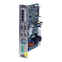
The digital Hall effect sensors (H1, H2 and H3) must be connected as shown below:
An external pull-up (resistor) must be added per sensor. A resistor of 1.5 kΩ (1/4 W) must be used if Vext is
equal to +15VDC. If the user needs to supply the Hall effect sensor with another voltage, please contact ETEL
to define the value of the resistor.
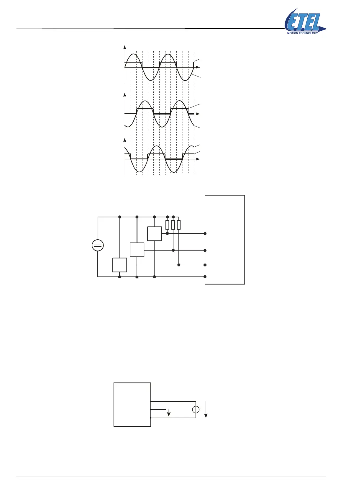
3.2.1.2 Digital outputs
To use a digital output, a voltage should previously be supplied to the external auxiliary supply (+Vext). This
voltage should range between +12VDC and +28VDC. The maximum total current provided by the digital
outputs is limited to 500 mA (limited by fuse F2).
It is recommended to use an external auxiliary supply (+Vext) as shown below (in this case, the logical value
‘1’ will correspond to +Vext and ‘0’ to GND ext).
Remark: This diagram shows the use of DOUT1, but it is the same with DOUT2.
Position
Position
Position
H1
H2
H3
V1-2
V2-3
V3-1
DSCDP
GND_EXT
H1+
H2+
H3+
2
3
4
5
Vext
H1
H2
H3
Rpull-up
DSCDP
+Vext
(+12VDC → +28VDC)
+Vext
DOUT1
GNDext
6
7
5
DOUT1
Artisan Technology Group - Quality Instrumentation ... Guaranteed | (888) 88-SOURCE | www.artisantg.com
 Loading...
