36 DSCDP Hardware Manual
ETEL Doc. - Hardware Manual # DSCDP / Ver G / 6/1/11
For the motor wiring, refer to the EN 60204/1 or NEC (UL) standard in order to use the
adequate cable section.
The DSCDP housed format already includes an in-built filter. An additional filter can be added (for
example (Schaffner FN2070-16-06) or a 'common mode choke' of 3mH (Schaffner RD6127-16-
3m0)) to reduce further electromagnetic disturbances.
For safety reasons, always connect first the protective earth (PE) to the screw under the DSCDP!
Remark: The tightening torque for the screws of the power input connector is 0.6 Nm max.
3.5.3 Connector JC12: Housed format, auxiliary supply input
This connector is only present on the DSCDPxx4-xxx format.
For safety reasons, always connect first the protective earth (PE) to the screw under the DSCDP!
Remark: The tightening torque for the screws of the auxiliary input connector is 0.25 Nm max.
•The power stage relay (24 VDC / 2880 Ω) allows the user to cut the +15 VDC voltage supplying the IGBT
gate driver, when the +24 VDC supply input of this relay is stopped.
If the power stage relay is not powered, the IGBT gate driver is deactivated (IGBT opened) and no power
is present on the motor's output. The power stage relay must then be powered (pin 4 to 0 V and pin 5 to
+24 VDC) to have power on the motor's output (otherwise an ’Inrush error’ will appear).
•The motor's short-circuit relay (+ 24 VDC / 490 Ω), which is optional, allows the user to short-circuit the
motor's phases.
If this relay is not powered, the motor's phases are shorted. The motor's short-circuit relay must then be
powered (pin 1 to +24 VDC) to have power on the motor's output.
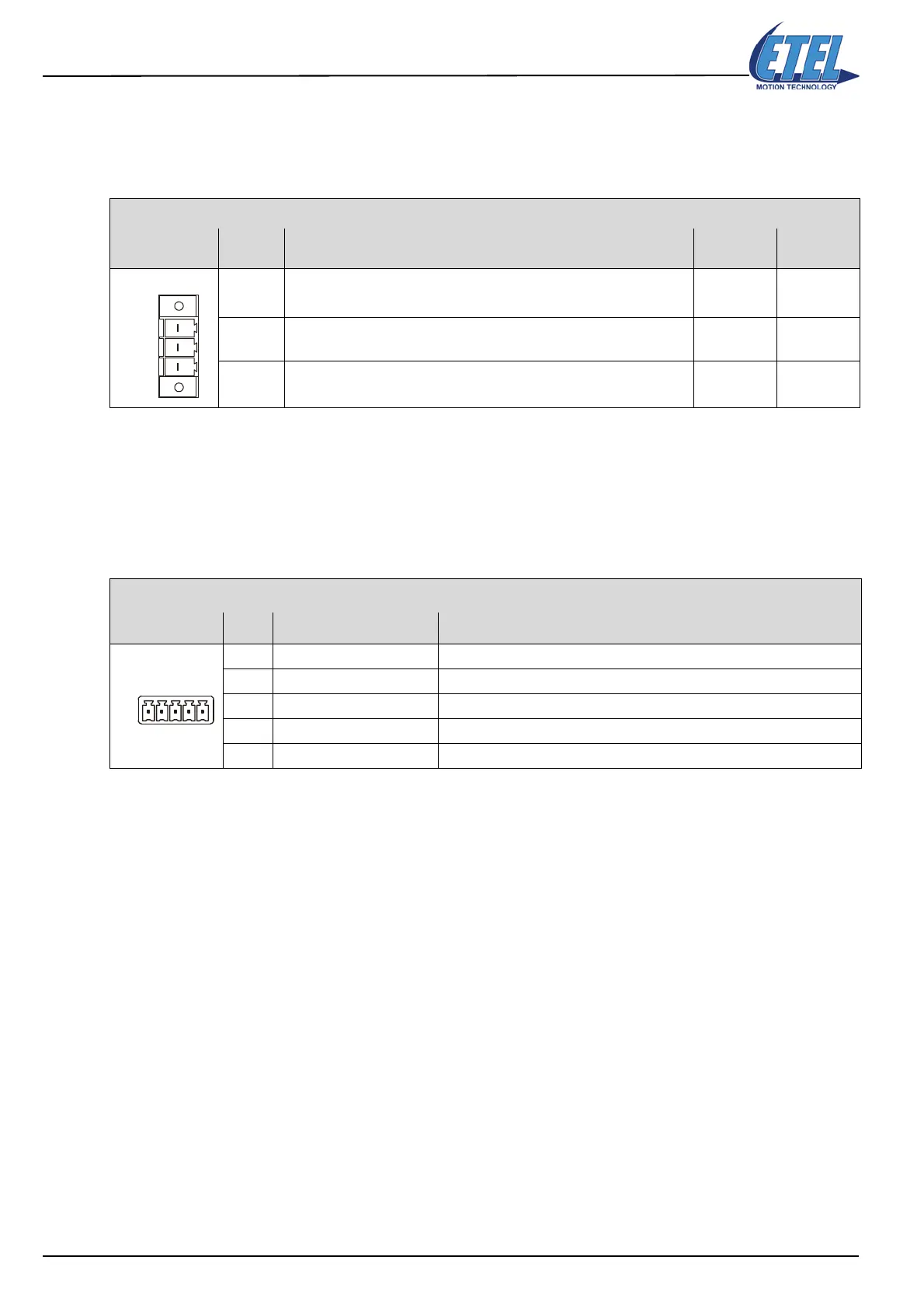
Phoenix Contact PC 4/3-G-7.62 (plastic connector)
POWER INPUT Signal Function
3-phase
mains
1-phase
mains
L1 Mains input for power supply (84 to 280 VAC MAX, between L1-L2) Mains L1 Mains L1
L2 Mains input for power supply (84 to 280 VAC MAX, between L2-L3) Mains L2 Mains L2
L3 Mains input for power supply (84 to 280 VAC MAX, between L3-L1) Mains L3
Do not
connect
Phoenix Contact MC 1.5/5-STF-3.81 (plastic connector)
AUXILIARY INPUT Pin # Signal Function
1 Optional short-circuit relay Motor's short-circuit relay supply input (24 VDC (referred towards GNDaux))
2 GNDaux Auxiliary supply input (0 V)
3 Vaux Auxiliary supply input (24 VDC)
4 Power stage relay - Relay supply input (0 V)
5 Power stage relay + Relay supply input (24 VDC)
Artisan Technology Group - Quality Instrumentation ... Guaranteed | (888) 88-SOURCE | www.artisantg.com
 Loading...
