ETEL Doc.- Hardware Manual # DSCDP / Ver G / 6/1/11
DSCDP Hardware Manual 39
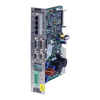
3.7.1.2 The motor cable
Caution: In order to respect the EMC standard, the following motor connector must be used.
Remark: The cable's radius of curvature must be taken into account to adjust the distance between the
front plate of the controller and the cabinet.
If a motor cable with a small diameter is used, turn the metallic clamp over to maintain the
shield continuity.
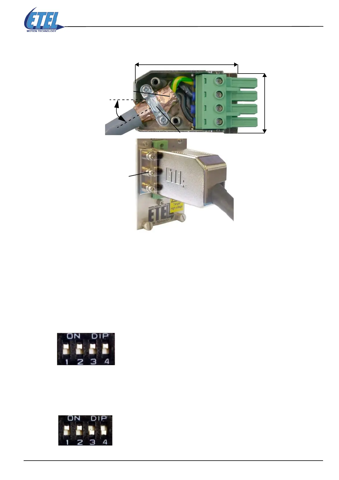
3.8 Axis number selection
It is possible to assign or to change the axes number of the controller with a DIP switch. After each starting, the
controller takes the axis number given by the DIP switch except when all the white switches are in the high
position which means set to 1 (like in the picture below). In this case the axis number is set by the AXI command
or the value previously saved in the controller or by the default value always equal to 1 (this default value is
used when no AXI command has been executed or no save has been done).
As there are 16 possible values on the DIP switch for 30 axes maximum (0 to 29), the number of the first axis
of a controller will be equal to the value given by the DIP switch multiplied by 2. The second axis' number of
the same controller will be automatically incremented by one.
Example:
The value given on the DIP switch represents a binary value (16 possibilities).
The axis number given by this DIP switch is equal to: 2
0
+ 2
1
= 3. Then, the first
axis of this controller will have the number 6 and the second one the number 7.
Shield contact
on 360°
Metallic cable clamp
Screws connecting the motor
connector to the front panel
of the controller
60.6 mm
36.18 mm
30°
Artisan Technology Group - Quality Instrumentation ... Guaranteed | (888) 88-SOURCE | www.artisantg.com
 Loading...
