Installation and Operation manual ETHOS 36C and ETHOS 54C –1511/05-issue1
Page 10
3.9 Condensate discharge
The condensate discharge must be installed during the assembly. Install the condensate discharge as follows:
Slide the supplied cup bottle trap over the two condensate hoses under the boiler, so the arrows are facing each
other. Then push the cup against the bottom of the boiler.
Turn the trap in position until the condensate discharge faces the desired direction. Attach the condensate discharge
hose to the trap with a plastic swivel and seal. The connection is linked to a suitable drain via the flexible hose.
Only use plastic parts for the condensation discharge. Metal pipes are not allowed.
Attention!
If this discharge is blocked, the appliance may be damaged.
3.10 CH and DHW circuit
3.10.1 Attention! Important
If plastic central heating pipe is used on the system, it should be a
barrier protected against oxygen diffusion.
On existing installations, the system should be fully cleaned and
flushed, with a suitable strainer being installed in the return pipe work
before being connected to the boiler.
3.10.2 CH circuit
The supply and return connections are based on connecting the
installation by using compression fittings.
These connections are located at the bottom of the appliance.
It is essential to install isolation valves for service purposes. The
appliance has a drain cock at the bottom, so it can be easily drained.
ATTENTION !
The appliance is not equipped with a pressure relief valve; A suitable
valve normally with a 3 bar setting must be installed in the installation's pipe work, in the immediate vicinity of the
appliance.
ATTENTION !
The appliance is not equipped with an internal bypass. A suitable automatic bypass valve should be fitted in
accordance with current regulations, and at such a distance from the boiler as to allow suitable flow rates.
Before the installation is operated for the first time, it must be thoroughly flushed and treated with suitable system
cleaners and inhibiters.
3.10.3 Expansion Vessel
The boiler is not fitted with an internal expansion vessel; so an expansion vessel should be sized to suit the volume
of water in the central heating installation and static pressure. The expansion vessel should be connected to the
return pipe work.
3.10.4 Main Cold Water Inlet
In the cold water pipe of the appliance a flow restrictor (Ethos 36 only) (par 2.2, No. 11) is mounted, used for
setting a restriction according the appliance's hot water rate (see table 3). There is no adjusting valve in the Ethos
54C combination boiler.
Connect the pipes according to statutory regulations.
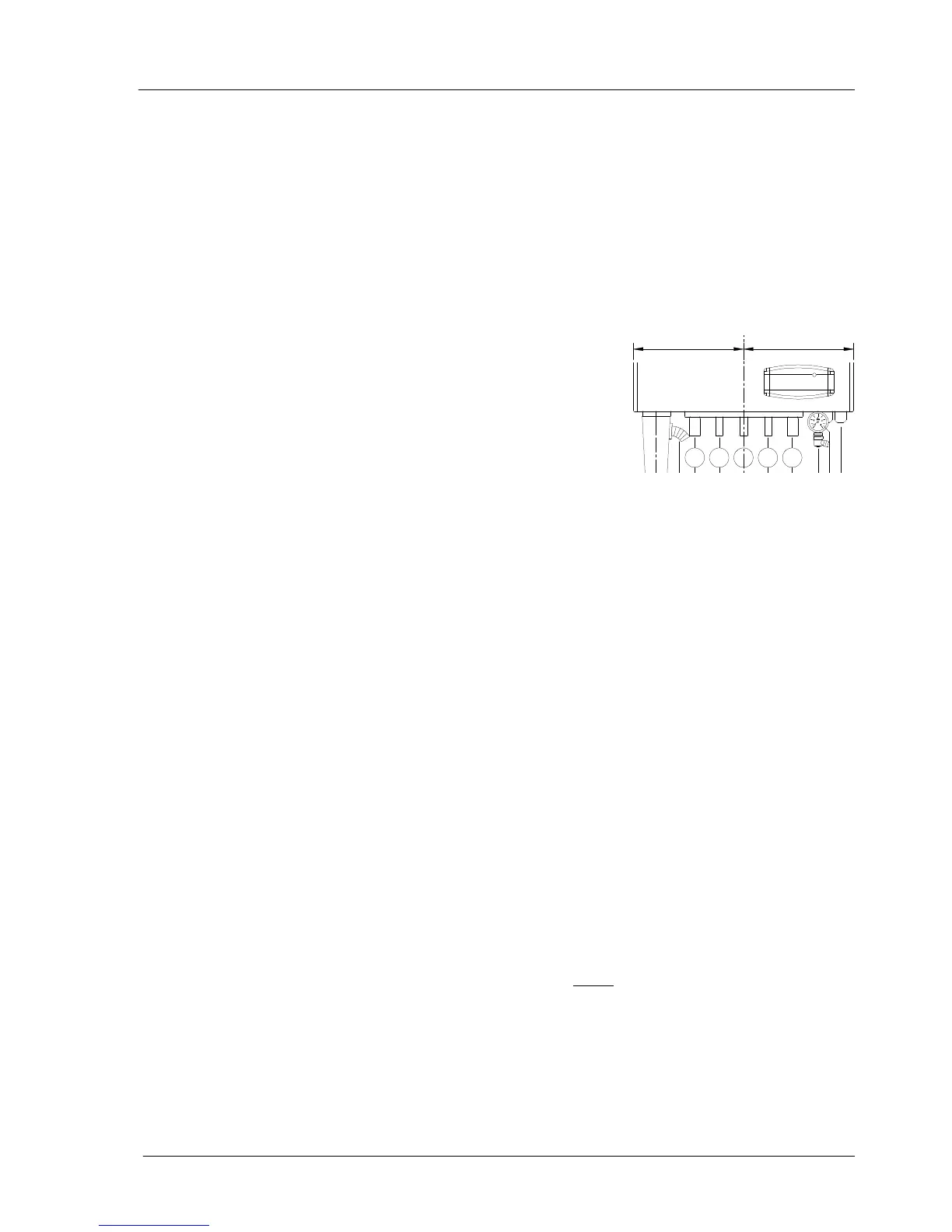
5050 5050
= =
1 = sifon spoelleiding
2 = CV aanvoer
3 = warm sanitair
4 = gas
5 = koud sanitair
6 = CV retour
7 = aftapkraan
8 = manometer
9 = kabeldoorvoer (3x)
10 = sifon afvoer
1
2
3
4
5 6
7
910
8
1= Condensate trap
2= CH supply
3= Domestic hot water connection
4= Gas
5= Cold water sanitary fittings
6= CH return
7= Drain cock
8= Pressure gauge
9= cable glands 3x
10= Condensate trap