Installation and Operation manual ETHOS 36C and ETHOS 54C –1511/05-issue1
Page 7
20
25
30
35
40
45
50
55
60
0 50 100 150 200 250 300 350 400 450 500
Pressure drop [Pa]
DHW heat input (Net) [kW]
36C
54C
3.4 Flue System
General
Air supply material: PP plastic or stainless steel
Flue discharge material: plastic (temperature resistant up to 120° C, air flushed) or stainless steel
Attention!
First connect all pipes and fill up and bleed the installation before commissioning the boiler.
The high flue gas temperature protection for plastic discharge material is built into the boiler as a safety feature. This
protection cuts off the gas supply as soon as the flue temperature gets too high, after which the appliance is
interlocked and error code 't0' starts to flash.
There are two types of connections:
• Concentric connection (80mm / 125mm with one pipe inside the other)
• Two Pipe system (80mm air intake with a separate 80mm Flue outlet)
Concentric connection (standard)
The concentric connection kit is standard: diameter air supply pipe 125 mm and flue pipe 80 mm.
Always place the plastic supply connection on top of the air inlet connection.
Two Pipe System (optional)
The optimal connection for air supply and flue pipes is obtained by using a stainless steel or plastic discharge
system.
The connection diameter for the flue pipe is 80 mm and for the air supply pipe also 80 mm.
The air supply pipe can be placed on the left or right side of the flue pipe by moving the connecting tube
3.5 Supply and discharge system
The Ethos boiler is a room sealed appliance with the air needed for combustion being drawn in from outside. The
casing jacket is sealed airtight to the back plate, so air can only be supplied through the air supply pipe. Therefore,
always make sure that the front door is placed on the appliance when the boiler is operating.
Attention!
Note that any horizontal flue pipe must be sloped back toward the boiler at a rate of 10mm per 1 metre. If not,
condensation can accumulate in the flue pipe, and may result in water damage to the boiler.
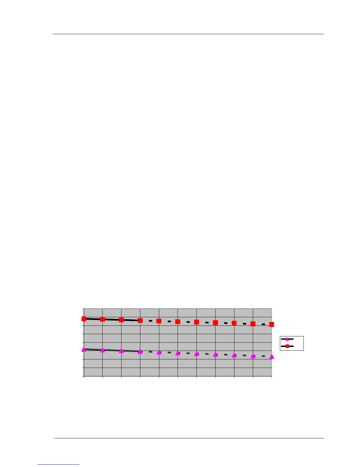
3.6 Influence of flue system on heat input
The diagram shows the ratio between the kW input and the flue systems resistance. For the maximum
Boiler output a resistance of 150 Pa or less is used.
Should the flue resistance be more than 150Pa the boilers output will be reduced; of further information contact the
technical department.