Installation and Operation manual ETHOS 36C and ETHOS 54C –1511/05-issue1
Page 12
4 ASSEMBLY INSTRUCTIONS FOR ELECTRICIAN
4.1 Mains connection
The boiler requires an earthed 230 volt 50 Hz single phase supply and must be connected in accordance with all
current regulations and requirements. A permanent supply to the boiler is needed at all times to the boiler, which
should be protected by a maximum 3 Amp double-poled isolator with at least 3mm of contact separation on both
poles.
The single phase cable colour coding should be wired correctly, although the boiler is not polarity sensitive
All control switching is volt free.
ATTENTION!
AT NO TIME SHOULD 230 VOLT BE USED TO SWITCH THE BOILER.
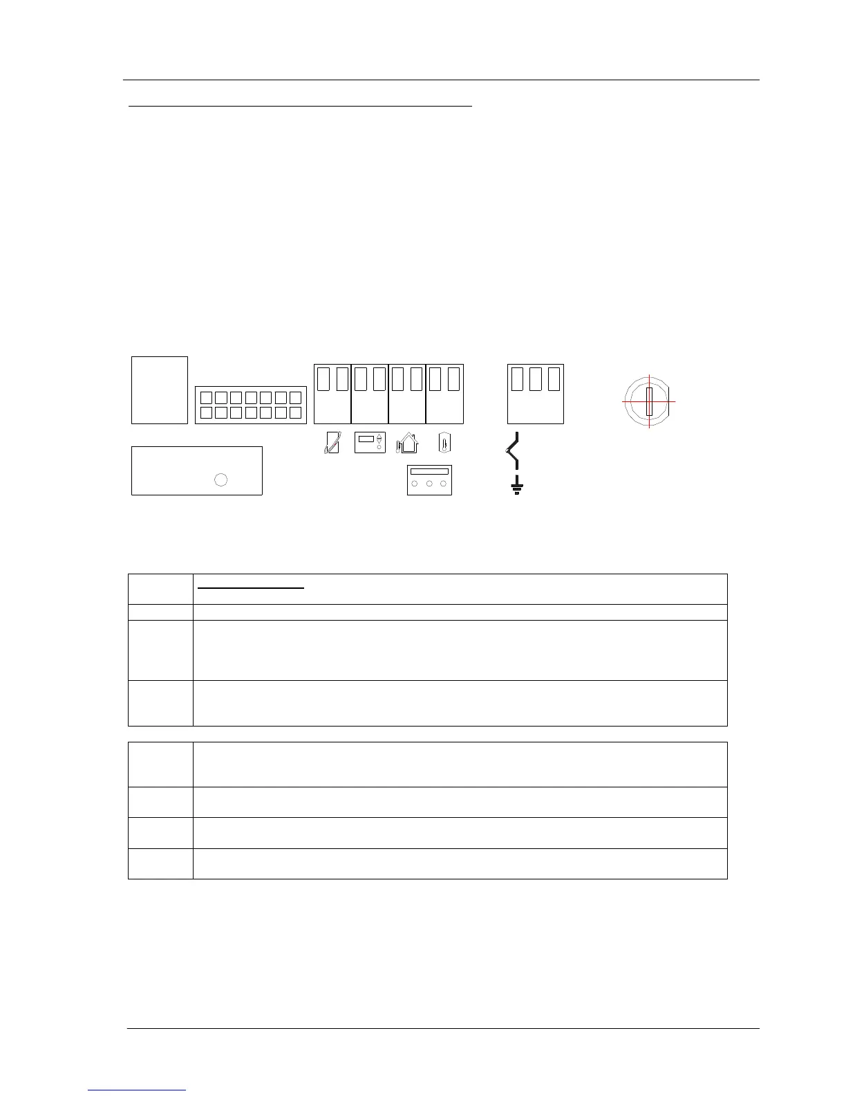
4.2 Terminal block connections
The following parts can be connected to the terminal block, see illustration
PC COM PC communication. The manufacturer can use this connection for reading-out or modifying data or
settings by using a PC and connecting cable.
1-2 OpenTherm® room thermostat / time clock. Can be used to fully modulate the boiler.
3-4. On/off room thermostat / time clock. For connecting clock or conventional room thermostats. The
heat acceleration element of the on/off thermostat must be set at 0.12A; the max. permissible
resistance of the room thermostat circuit should not exceed 10 ohm.
Attention! Do not connect an OpenTherm® room thermostat to this terminal.
5-6. Outside temperature sensor. If an OpenTherm® thermostat with weather dependent control is
used, the outside temperature sensor must be connected to terminals 5 and 6. The OpenTherm®
thermostat contains the settings for weather dependent control.
7-8 External DHW cylinder. The external water heater can be connected to the boiler with a sensor
(NTC) or thermostat; if a sensor is used, the boiler display can show the water heater temperature.
Only applicable for Ethos …SD boilers
PE. N. L Power supply connection 230V. Connection for earthed cable.
PE= earth N= Neutral L= phase 230V 50Hz
CODE
KEY
Code key. A code key is a small PCB which contains the settings per boiler type. When the burner
control unit is replaced, the code key must be installed in the new burner control unit.
ALARM
External failures. This connection can be used for showing external messages by using a relay on
terminals 1 and 3. A LED can be connected to terminals 2 and 3.
CODE KEY
PC
COM
ALARM
1 2
3
4
5 6
7
8
N L
PE N L
FUSE 2AT
Figure 6 Electric terminals
Table 4 Explanation of electrical connections