Manual EKS Electronic-Key Adapter USB
Page 12/34 Subject to technical modifications 2094485-05-07/19
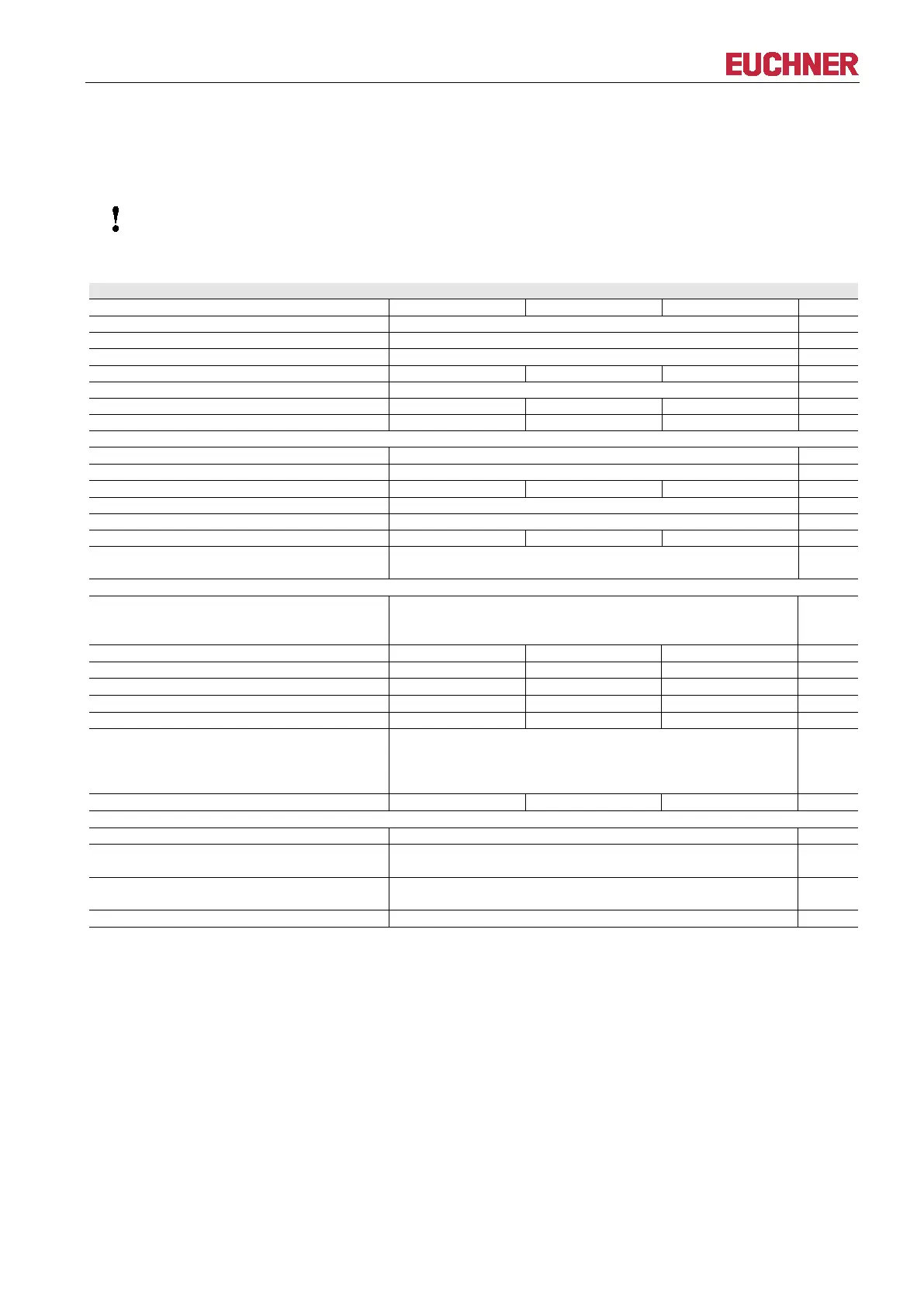
4.2 Technical data
4.2.1 Technical data for Electronic-Key adapter in G01 housing
All the electrical connections must either be isolated from the mains supply by a safety transformer
according to EN IEC 61558
-2-6 with limited output voltage in the event of a fault, or by other equivalent
IP65/IP67 in installed state
Mounting cut-out acc. to DIN IEC 61554
USB Full Speed (compatible with all USB versions)
1 start bit, 8 data bits, 1 parity bit (even parity), 1 stop bit
Green: “Ready” (in operation)
Yellow: “Electronic-Key active” *
Version FSA (For Safety Applications) – parameters for floating semiconductor switching contacts LA and LB
Switching contact connection
Plug-in connection terminal, 4-pin,
with screw terminal (tightening torque 0.22 Nm), conductor
cross-section 0.14 ... 1.5 mm²
Power supply U for load (LA, LB)
Switching current (with overload protection)
Output voltage U
A
(LA, LB) in switched state
Resistance in switched state
Utilization category acc. to AC-12
EN IEC 60947-5-2 AC-15
DC-12
50 mA / 24 V
Difference time of the outputs** (LB first)
Reliability values acc. to EN ISO 13849-1 (FSA version only)
Category (with downstream safe evaluation)
d
Evaluation of data channel and one
switching contact LA
416 years
Evaluation of data channel and both
switching contacts LA and LB
803 years
* The LED illuminates yellow if there is a functional Electronic-Key in the Electronic-Key adapter.
** If the USB interface is accessed during placement or removal of the Electronic-Key,
the difference time can be more than 200 ms.