Do you have a question about the EUCHNER EKS and is the answer not in the manual?
This manual describes the technical features and function of the EKS Electronic-Key adapter.
Lists abbreviations used in the manual.
States conformity with EMC directive and relevant standards.
Mentions certification according to US standards and power supply requirements.
Details proper usage of the EKS adapter in higher-level systems and safety considerations.
Outlines responsibilities for observing safety regulations.
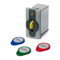
Explains the purpose and operation of the EKS adapter and Electronic-Key.
Details extra functions for the EKS FSA version, including relay outputs.
Provides technical drawings and dimensions for adapter installation.
Lists detailed technical specifications and parameters of the adapter.
Details the USB socket and screw terminal connections.
Explains the configuration options using DIP switches S1 to S8.
Describes the meaning of the LED colors for operating states.
Specifies USB cable requirements and connection procedures.
Details wiring for EKS FSA outputs and safety considerations.
Illustrates a safety circuit with an enabling switch.
Explains the function and safety requirements of the enabling switch example.
Describes the feedback loop for safety relay operation.
Explains the start sequence for the safety relay.
Shows the circuit diagram for the enabling switch example.
Illustrates a safety circuit without an enabling switch.
Explains the function and safety requirements for the example without an enabling switch.
Describes the feedback loop for safety relay operation in this scenario.
Explains the start sequence for the safety relay in this scenario.
Shows the circuit diagram for the example without an enabling switch.
Step-by-step guide for installing USB drivers on Windows XP.
Step-by-step guide for installing USB drivers on Windows 7.
How to change the COM port and view driver version.
Step-by-step guide for uninstalling USB drivers.
Explains USB interface features like virtual COM port and LED indication.
Describes PC to adapter communication via virtual COM port and protocol.
Details the message structure for commands using the 3964R protocol.
Explains the reliability and features of the 3964R protocol.
Details the 3964R protocol, control characters, and data integrity.
Explains how the control system sends data and handles acknowledgments.
Explains how the control system receives data and handles errors.
Summarizes key points like DLE duplication and block check character.
Outlines commands for writing and reading data to the Electronic-Key.
Details the command message and reply message for writing data to the key.
Details the command and reply messages for reading data from the key.
Explains how to read the unique 8-byte serial number of the Electronic-Key.
Provides a summary table of available commands and their replies.
Lists and explains the status codes returned by the system.
| Category | Adapter |
|---|---|
| Type | EKS |
| Operating Voltage | 24 V DC |
| Current Consumption | ≤ 100 mA |
| Protection Class | IP67 |
| Ambient Temperature | -25°C to +70°C |
| Connection | M12 connector |