Manual EKS Electronic-Key Adapter USB
Page 14/34 Subject to technical modifications 2094485-05-07/19
4.3 Connector assignment
4.3.1 USB interface socket in G01 housing
The socket on the Electronic-Key adapter is designed as USB type B.
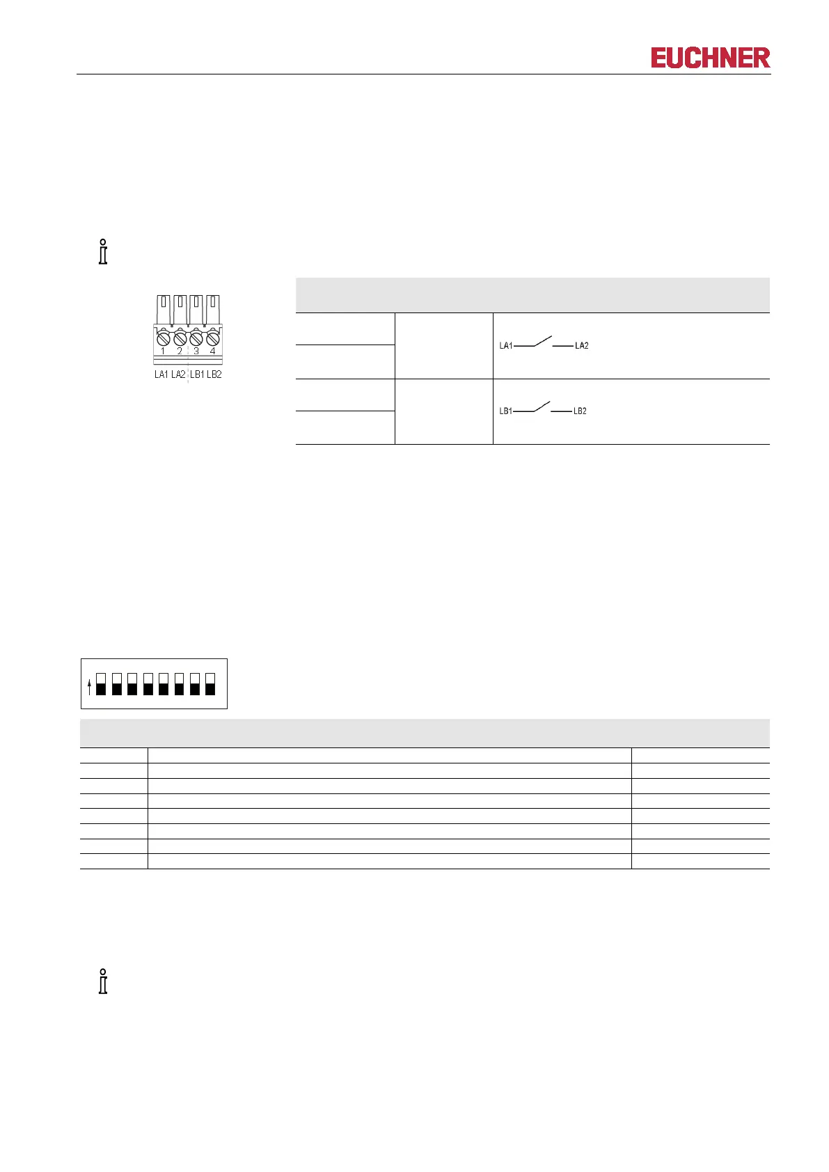
4.3.2 Screw terminals of switching contacts LA1/LA2 and LB1/LB2 (EKS FSA only)
-in connection terminal is included with the Electronic-Key adapter.
Plug-in connection terminal,
2 x 2-pin,
with screw terminal
Pin Channel Function
1
LA
NO contact, channel LA
2
3
LB
NO contact, channel LB
4
4.3.3 USB interface socket in G30 housing
The socket on the Electronic-Key adapter is designed as USB type Mini-B.
4.4 DIP switch settings (only in G01 housing)
Using the DIP switches S1 to S8, various parameters can be set.
Write protection can be enabled using DIP switch S1. In this way the writing of data to the Electronic-Key
read/write is prevented.
The settings are adopted only when the power supply is switched on.
DIP switches, 8-switch:
Functions Factory setting
OFF = Electronic-Key read/write ON = Electronic-Key read-only *
ON = write protection for Electronic-Key read/write
The read-only transponder type can also be read using the Electronic-Key adapter with USB interface. However, we do
not recommend using this transponder type in new installations. The read-only transponder cannot be used in
conjunction with the version EKS FSA.
imperative that all DIP switches without a function (S2 to S7) are set to OFF! In this way problems
with any functions added in the future will be avoided.