8
Operating Instructions
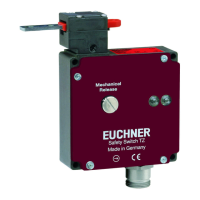
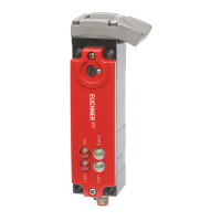
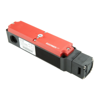
Safety Switch TP…
Notes about
The following information applies to devices
with cable entry:
For use and application as per the requirements
of a copper wire for the temperature range
60/75°C must be used.
The following information applies to devices
with plug connector:
This device is intended to be used and applied with
a Class 2 power source in accordance with UL1310.
Connecting cables for safety switches installed at
the place of use must be separated from all moving
and permanently installed cables and un-insulated
active elements of other parts of the system that
operate at a voltage of over 150V. A constant
clearance of 50.8mm must be maintained. This
does not apply if the moving cables are equipped
with suitable insulation materials that possess an
identical or higher dielectric strength compared to
the other relevant parts of the system.
EU declaration of conformity
The declaration of conformity is part of the oper-
ating instructions, and it is included as a separate
sheet with the unit.
The original EU declaration of conformity can also
be found at: www.euchner.com
Service
If servicing is required, please contact:
EUCHNER GmbH + Co. KG
Kohlhammerstraße 16
70771 Leinfelden-Echterdingen
Germany
Service telephone:
+497117597-500
E-mail:
support@euchner.de
Internet:
www.euchner.com
Technical data
Parameter Value
Housing material Reinforced thermoplastic
Degree of protection
acc. to IEC60529
Cable entry
Plug connector SR6/SR11
IP67
IP65
Mechanical life 1 x 10
6
operating cycles
Ambient temperature -20 … +55 °C
Degree of contamination
(external, acc. to EN60947-1)
3 (industrial)
Installation orientation Any
Approach speed, max. 20 m/min
Extraction force (not locked) 20 N
Retention force 10 N
Actuating force, max. 10 N
Actuation frequency 1,200/h
Switching principle Slow-action switching contact
Contact material Silver alloy, gold ashed
Connection
TP…
TP…SR6
TP…SR11
Cable entry
Plug connector SR6, 6-pin+PE (PE
not connected)
Plug connector SR11, 11-pin+PE
(PE not connected)
Conductor cross-section
(exible/rigid)
0.34 … 1.5 mm²
Operating voltage for optional
LED indicator
L024 24 V
Rated insulation voltage
TP…, TP…SR6
TP…SR11
U
i
= 250 V
U
i
= 50 V
Rated impulse withstand voltage
TP…, TP…SR6
TP…SR11
U
imp
= 2.5 kV
U
imp
= 1.5 kV
Conditional short-circuit
current
100 A
Switching voltage, min.,
at 10mA
12 V
Utilization category acc. to EN60947-5-1
TP…, TP…SR6 AC-15 4 A 230 V /
DC-13 4 A 24 V
TP…SR11 AC-15 4 A 50 V /
DC-13 4 A 24 V
Switching current, min.,
at 24V
1 mA
Short circuit protection
(control circuit fuse)
acc. to IEC60269-1
4 A gG
Convent. thermal current I
th
4 A
Solenoid operating voltage/solenoid power consumption
TP…024 AC/DC 24 V (+10%/-15%) 8 W
TP…048 AC/DC 48 V (+10%/-15%) 8 W
TP…110 AC 110 V (+10%/-15%) 10 W
TP…230 AC 230 V (+10%/-15%) 11 W
Duty cycle 100%
Locking force F
max
TP1/TP2/TP3/TP4
TP5/TP6
F
max
= 1,300 N
F
max
= 800 N
Locking force F
Zh
acc. to ENISO14119
(F
Zh
=
F
max
)
1.3
TP1/TP2/TP3/TP4
TP5/TP6
F
Zh
= 1,000 N
F
Zh
= 600 N
Reliability values acc. to ENISO13849-1
B
10D
at DC-13 100mA / 24V
3 x 10
6