ML530 Manual Version 1.0 Page 5 ©1999 Euphonix, Inc.
13) Cooling - In order to provide adequate ventilation for product cooling, Euphonix
recommends that One (1) rack space be left open on TOP of every two (2) box devices
except the S5 computers. . Examples of box devices are 2RU high converters, the
Mic/Line Interface and the Monitor Controller. The Mic-Line and the Monitor box must
be on the TOP of the group of two.
THERE ARE NO USER SERVICEABLE PARTS IN THE ML530
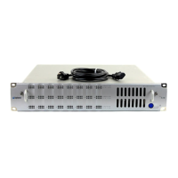
System Setup
The ML530 receives control information from the System 5 Interface Pilot via a 15 pin Dsub
cable.
All necessary connections to the ML530 are described in the cable specifications and hookup
diagrams in this document.
Power On Sequence
The ML530 can be powered up independently of the Digital Core components. It can be left
powered on continuously in a typical installation.
CE
CE certification for the ML530 is available from the factory.