ML530 Manual Version 1.0 Page 8 ©1999 Euphonix, Inc.
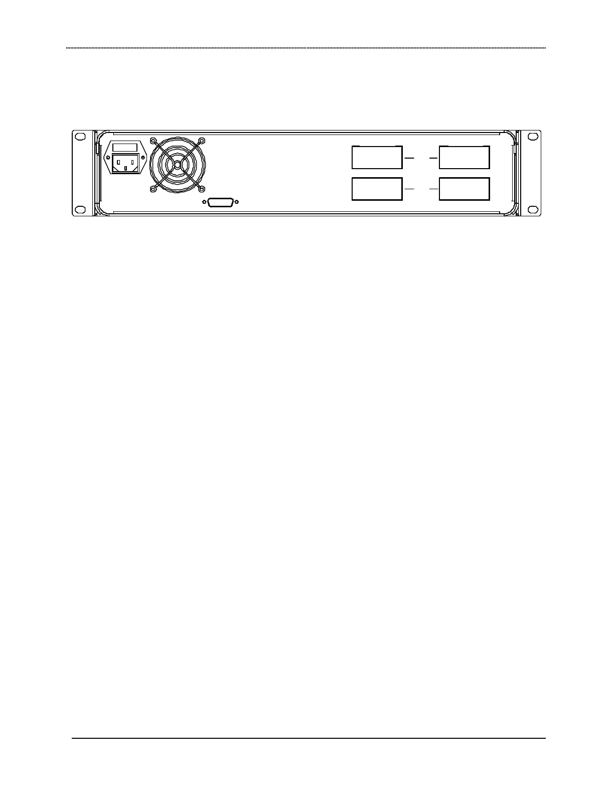
Rear Panel Connectors
Inputs (38 pin ELCO). A total of 24 inputs are provided on two 38 pin ELCO connectors. All signals
input at these ports can be level boosted or attenuated. In standard configuration, input cable is
configured by customer. ELCO connectors and pins are provided. (See pinouts on pages 14
and 15.)
Outputs (38 pin ELCO) A total of 24 outputs are provided on two 38 pin ELCO connectors. The supplied
output cables fan out to 2 sets of 12 XLR Females for connection to the AM713 Analog to MADI
converter. (See pinouts on pages 14 and 15.)
Control (DB15) Digital control input from 253i Pilot computer. Signal format is Euphonix TCC bi-
directional serial protocol.
AC Line In (IEC) and Fuse Tray The IEC power connector accepts standard IEC power cords. 90-250VAC,
50 or 60Hz can be applied at this connector.
Dimensions
Height: 3.5 inches
Width: 19 inches
Depth: 18.6 inches
Weight: 17 lbs
Approximately 6 inches of depth should be left behind the ML530 for cable connections.
CONTROL
OUTPUTS INPUTS
1 -12
13-24
ML530