PAGE
15/16
www.evb.com
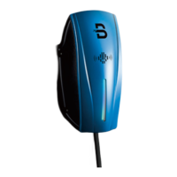
Step 3
Cut out on the back of the EV charger.
Find the hole for cut out on the back of EV charger.
Use the 4pcs M6*8 screws to fix the EV charger to the mounting plate as
picture shows (Screws torque 1.5NM-2.0NM).
Left hole position
Right hole
position
Back of EV charger
perforating
as image
M6*8 bolts
Power cable
wiring diagram
Insert power cord
into the top of
connection box
wiring diagram
Single-phase
Three-phase
wiring diagram
Cable box with built
-in cable throughEV
chargerwiring position
3.7.3. Step-by-step Installation Instructions (top entry wiring)
Step 4
Wiring
Note: Consult with your local electrician or refer to your local code for
proper wire sizing appropriate for the currents in your EV Charger.
Note: It is the installer's responsibility to identify whether additional
grounding is required to ensure that local regulations are met. Grounding
must be installed at the power source and not at the cable entry to the EV
Charger.
As the picture at left shows, use the screwdriver loosing the screws on the
EV charger cover. Wire the cable to the according terminal.
Note: The torque applied to the screws should be 1.8N-m to 2.2N-m
Warning
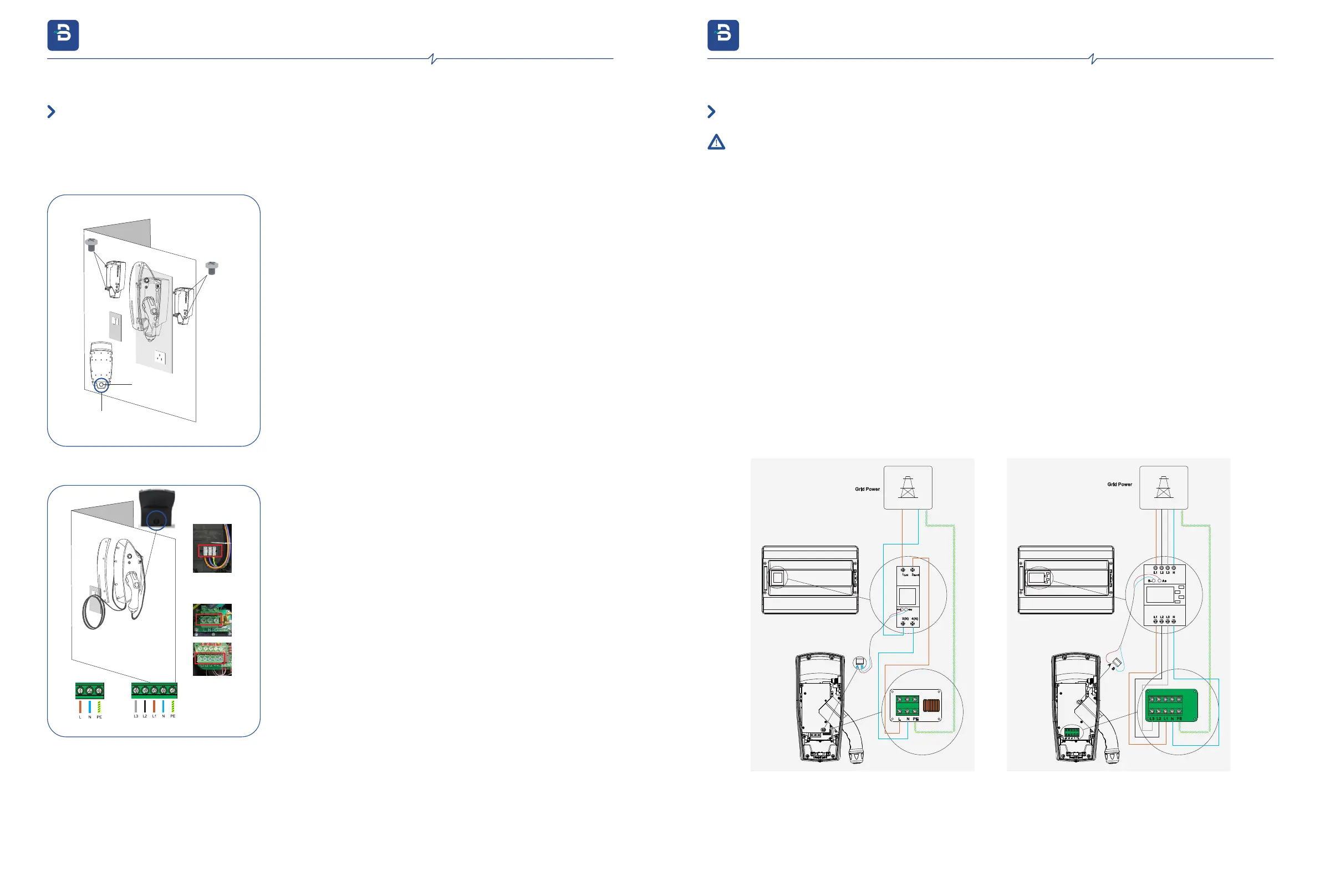
3.7.4. External Meter Installation
Do not connect the power cord before reading and fully understanding all the concepts introduced in this section. If you are not sure
whether the type of power supply on the repair panel is available, please consult an electrician for assistance.
Be careful of electric shock! Before use, use a voltmeter to confirm that there is no voltage on the power supply line or terminal to ensure
that the power has been cut off.
●
●
Disconnect the power supply at home, and find the neutral wire and the live wire at the entrance to the house.
According to the wiring figure, the live wire and the neutral wire are respectively connected to the power grid through cables that support
a current of more than 32A, so that the connection between the power meter and the power grid is completed.
According to the wiring figure, connect the live wire and neutral wire to the interfaces be reserved in the charger respectively through the
cables that support more than 32A , so that the meter is connected.
The AB interfaces on the meter needs to be connected to the AB interfaces in the charger PCB Via a cable that supports 485
communication.
The ground wire of the grid needs to be connected to the ground wire interface which is reserved in charger.
The meter has been configured to fit the charger by default, please do not change the configuration.
Please contact us for technology support if you are going to install meters are not from us.
●
●
●
●
●
●
Single Phase
Three Phase
3. Installation Instructions
evb.com
3. Installation Instructions
evb.com