EVC electronic GmbH -10- BDM100 Module
Interconnections for Daimler-Crysler ETC5 (P02) V1.1
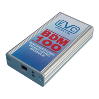
On the ETC5 ECU the power distribution ist
provided by the following contacts of the
"black" contact chamber (the other contact
chambers are marked with color bars).
The required contatcts for powering up the
ECU are shown in Picture A.
Use separate wires with matching
connectors to connect GND and +12Vcc to
these contact pins.
After removing the top lid of the ECU, you
can see, that the PCB is embedded in a
clear but sticky and wobbly silicone mass.
For some versions of the ETC5 ECU, a
BDM149 probe is used to contact the BDM-
pads on the board by poking the spring
contact pins through the silicone mass.
If you do not use a BDM149 probe, solder a
10-pin header onto the BDM-pads.
The position of pin1- location of the BDM-
pads is already marked in the PCB layout.
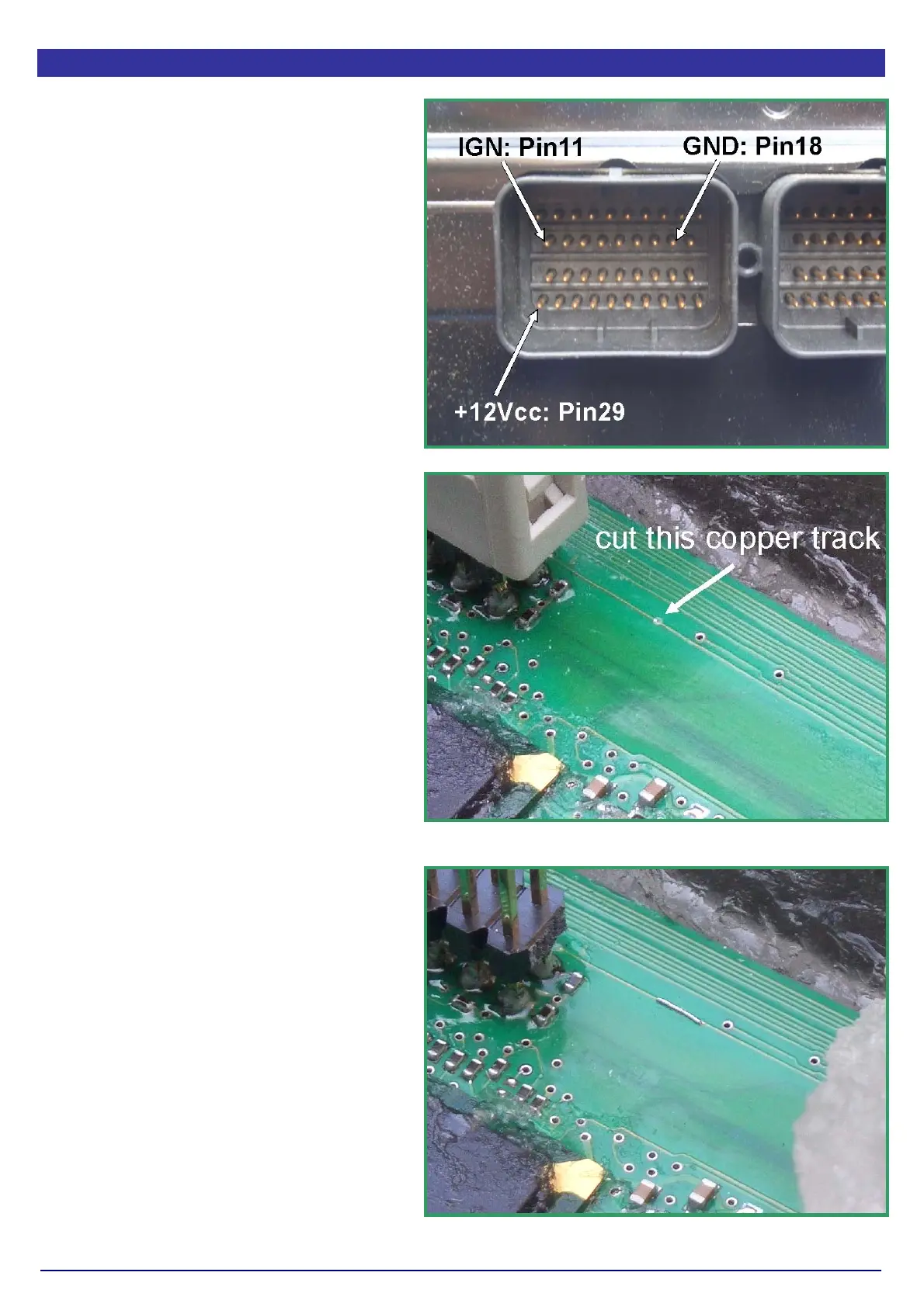
To make the P02- version of the ETC5 ECU
readable and programmable, a track on the
PCB must disrupted as shown in picture B.
For that operation, the silicone mass must
be removed.
If you then applying power to the main
connector of the ECU the red LED of the
BDM149 probe (if used) lights up to indicate
that the logic on the board is supplied with
the required voltage.
The BDM100 module is now operational.
After programming the ECU, it is recom-
mended to reconnect the disrupted PCB-
track as shown in Pictrure C.
Pict. A: The power connection on the ETC5 ECU.
Pict. B: The position ot the track that must dis-
rupted.
Pict. C The reconnected track on the ETC5 board.