EVC electronic GmbH -16- BDM100 Module
Interconnections Siemens HMC Theta PI ECUs
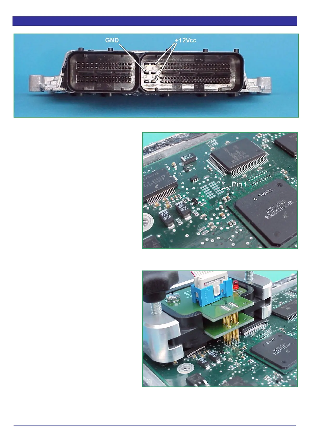
Pict. A: The main connector of the Siemens HMC Theta PI-ECU.
On the Siemens MS45 ECU the power
distribution is provided by the pins of the
main connector as shown in picture A.
Use separate wires to connect GND and
+12Vcc to the pins of the main connector
shown in picture A.
Now place the BDM144 probe into the
positioning frame and carefully put the tips
of the spring contact probes on the pads on
the board as shown in picture C.
If the length of the spring contact pins
should be to short, pull the spring contact
pins up to the first rest position from the
receptacles.
The tips of the spring contact probes should
reach a spring travel of 1mm minimum for
best contact conditions.
If you then applying power to the main
connector of the ECU the red LED of the
BDM144 probe lights up to indicate that the
logic on the board is supplied with the
required voltage
The BDM100 module is now operational
Pict. B: Only ten of the present 12 pads will be
used. The extra both are not connected.
Pict. C: The tips of the spring contact probes
should reach a spring travel of 2mm minimum for
best contact conditions