EVC electronic GmbH -12- BDM100 Module
Interconnections for Delphi DCM3.2 ECUs
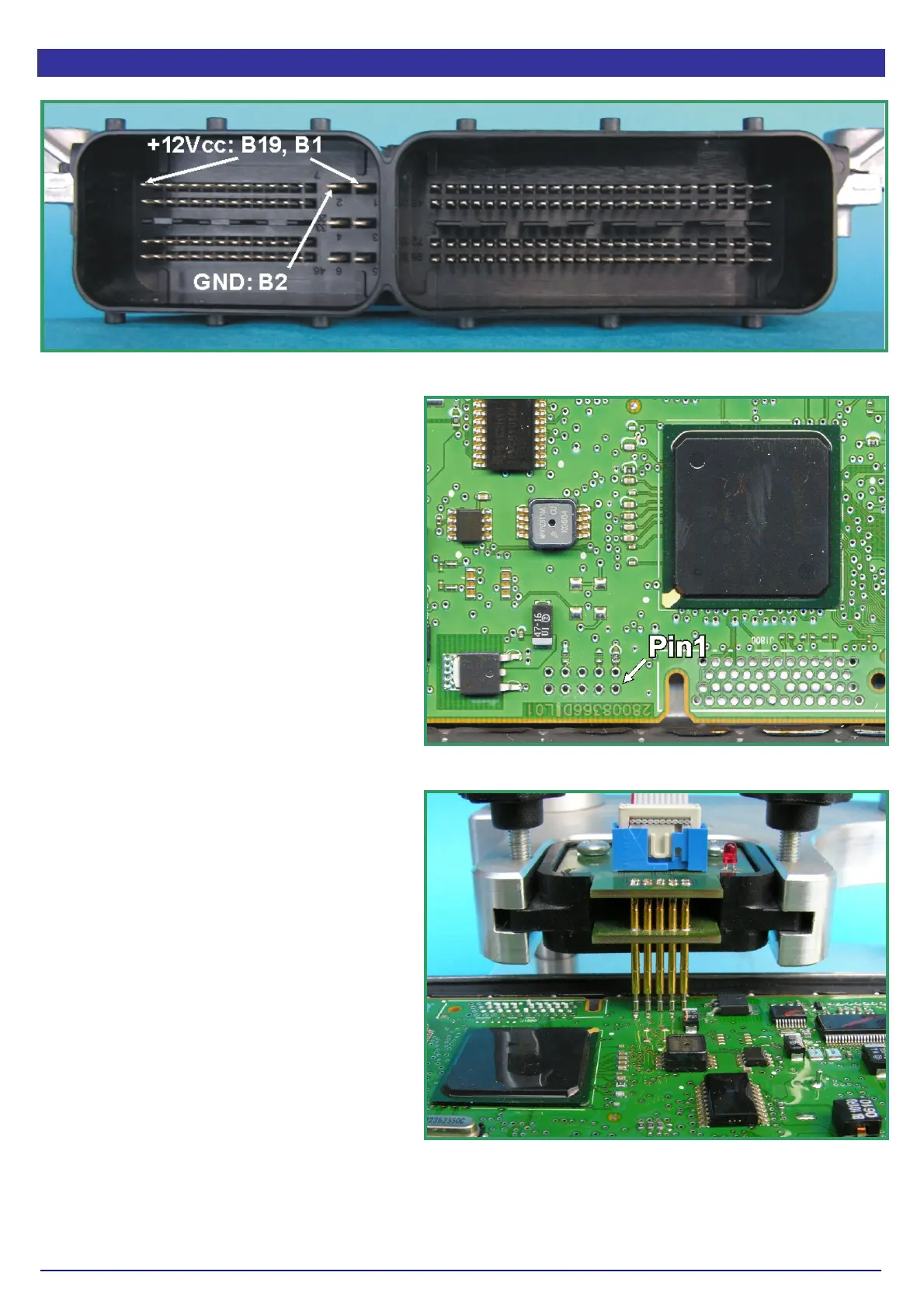
Pict. A: The main connector of the Delphi DCM3.2 ECU.
On the DCM3.2 the required contacts are
located in the smaller chamber of the main
connector (Pict. A)
Use separate wires with matching
connectors to connect GND and +12Vcc to
the pins of the main connector shown in
picture A.
Compared to the standard BDM pin out, the
pin out of the BDM-pads on that board is
mirrored, probably due the board was
programmed first in the factory before
mounting it into the case (PictB).
Now place a BDM147 probe into the
positioning frame and carefully put the tips
of the spring contact probes on the pads on
the board as shown in picture C.
The tips of the spring contact probes should
reach a spring travel minimum of 2mm for
best contact conditions.
If you then applying power to the main
connector of the ECU the red LED of the
BDM147 probe lights up to indicate that the
logic on the board is supplied with the
required voltage.
The BDM100 module is now operational.
Pict. B: The location of the required Pads.
Pict. C: Like that the BDM147 probe will be
positioned over the DCM3.2 board.