EVC electronic GmbH -8- BDM100 Module
Interconnections Bosch ME9.7 ECUs
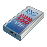
Pict. A: The main connector of the Bosch ME9.7 ECU.
On the Bosch ME9.7 ECU the power
distribution is provided by the pins of the
main connector.
Use separate wires with matching
connectors to connect GND and +12Vcc to
the pins of the main connector shown in
picture A.
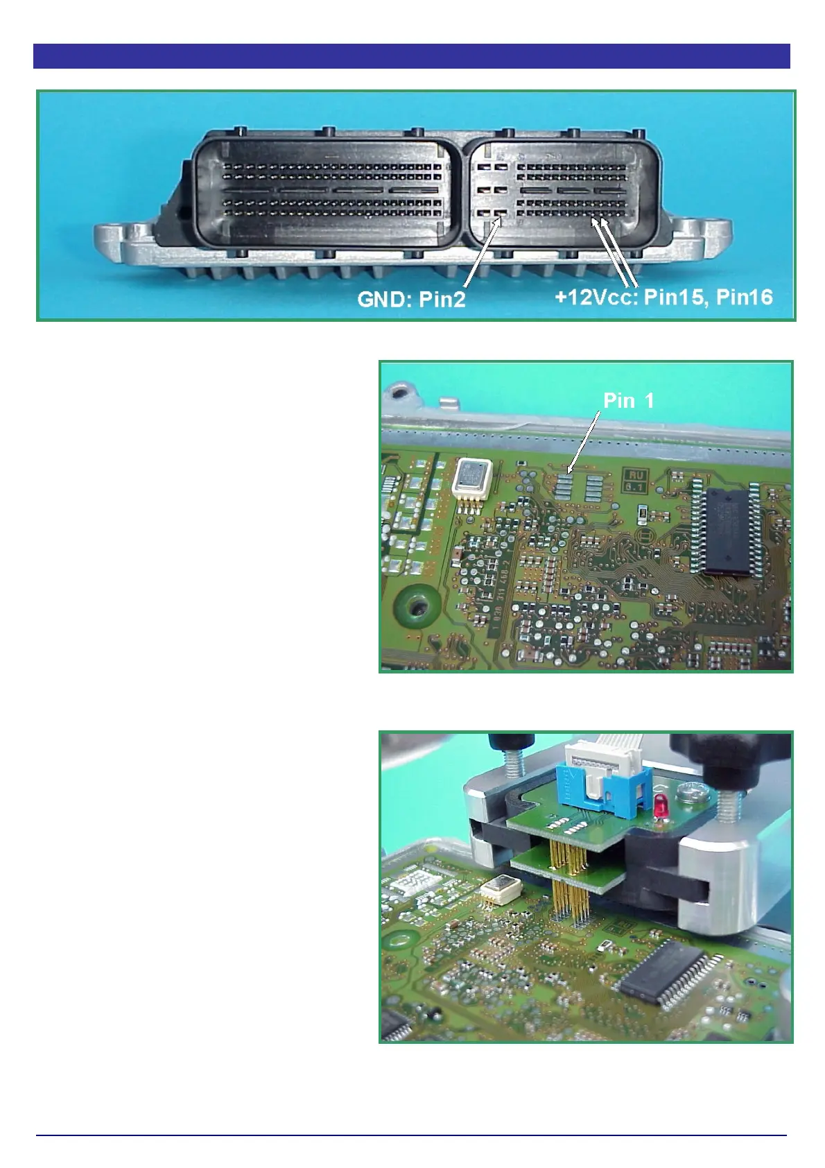
Now place a BDM141 probe into the
positioning frame and carefully center the
tips of the spring contact probes on the
BDM-pads on the board as shown in
picture B.
The tips of the spring contact probes should
reach a spring travel of 1.5 mm minimum for
best contact conditions.
Then connect the BDM110 flat wire cable to
the BDM100 module which should already
connected to your computer.
If you then applying power to the main
connector of the ECU the red LED on the
BDM141 probe lights up to indicate that the
logic on the board is supplied with the
required voltage
The BDM100 module is now operational.
Pict. B: This are the required pads for the BDM
Interface.
Pict. C: This way the BDM141 probe contacts the
board of the Bosch ME9.0 ECU..