EVC electronic GmbH -33- BDM100 Module
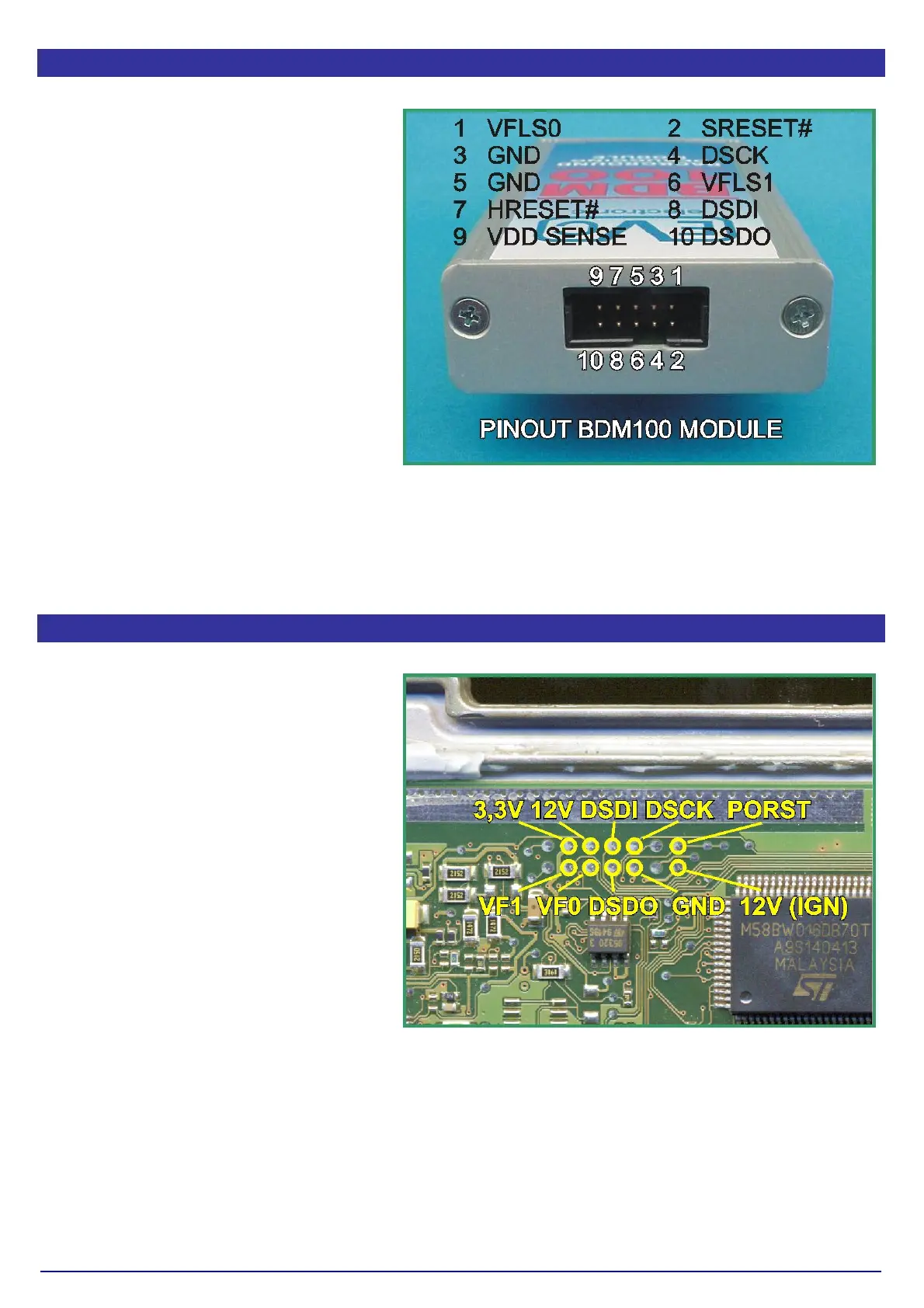
Pin Out BDM100 Module
Picture A shows the pinout of the 10way
pin header located on the back of the
BDM100 Module.
This pinout appropriates the standard
BDM port pinout.
On ECUs equiped with a 10way BDM-
port the interconnection can made by
using a simple 10way flat- wire cable. In
this case the location of pin 1 of the BDM-
port on the ECU board should be known.
Pict. A: The pinout of the 10way pin header
Pin Out BOSCH System Programming Pads
The pad arrangement of the BOSCH
ECUs differs from the MOTOROLA
standard.
The 12Vcc clamp voltage from the battery
and also the !2Vcc from the Ignition or
wake up circuit are present in that pad
array.
Picture B shows which signals and
voltages were assigned to the pads.
Please consider that in early EDC16
ECUs the 3.3V pad is driven by a 5V
circuit.
Pict. B: The pinout of the BOSCH programming pads.