EVC electronic GmbH -15- BDM100 Module
Interconnections Marelli ECUs
The BDM110-cable is made for
connecting the BDM100 module with
ECUs using a 10way standard BDM-port
with a 0.1’ pitch.
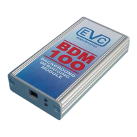
On a Marelli board you will find a 12pad
array with 0,05’ pitch for the BDM port.
Two of them, pad 11 and pad 12 are
unused (pitcure D).
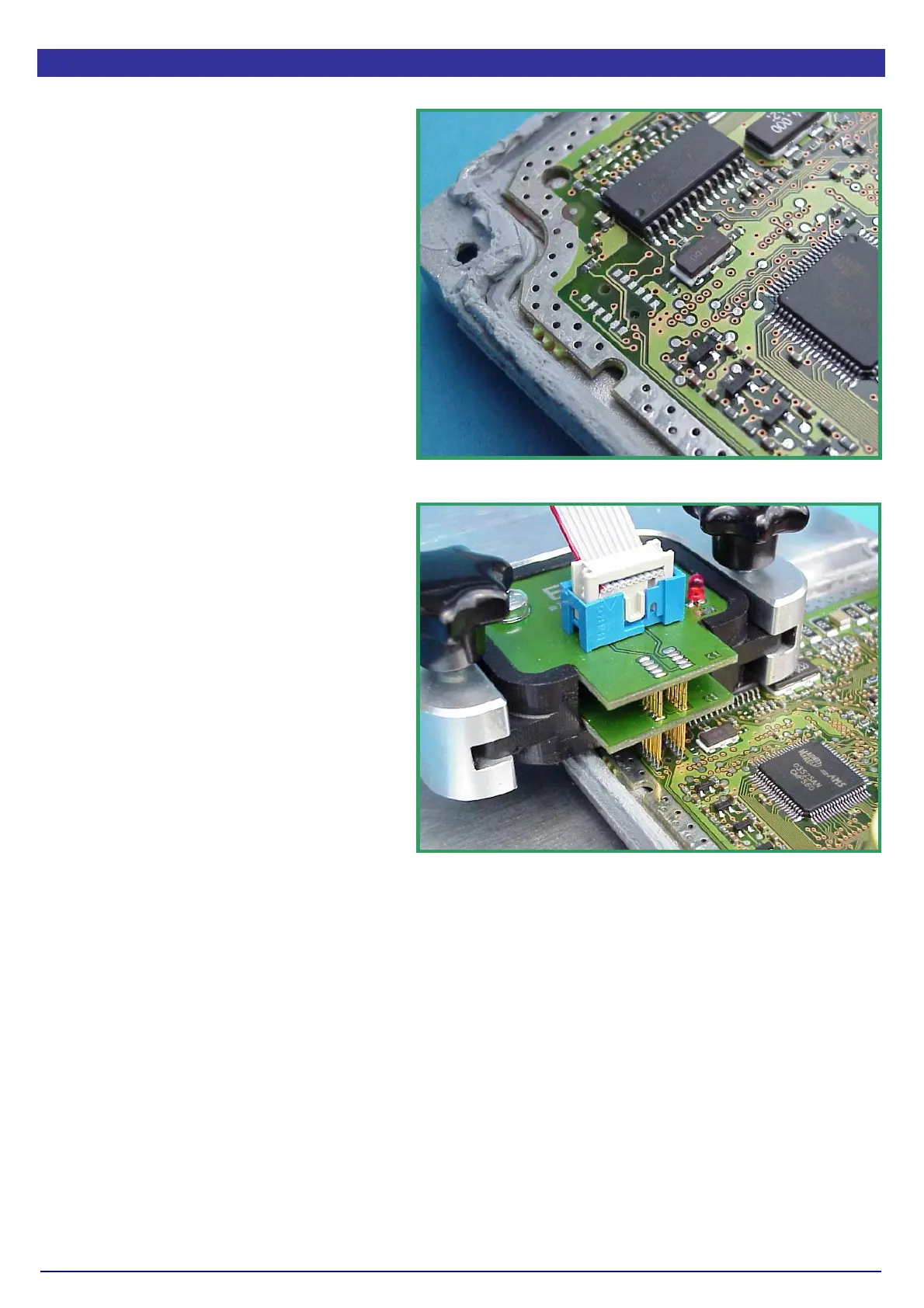
Now place the BDM144 probe into the
positioning frame and carefully put the tips
of the spring contact probes on the pads
on the board as shown in picture E.
If the length of the spring contact pins
should be to short, pull the spring contact
pins up to the first rest position from the
receptacles.
The tips of the spring contact probes
should reach a spring travel of 2mm
minimum for best contact conditions.
If you then applying power to the main
connector of the ECU the red LED of the
BDM144 probe lights up to indicate that
the logic on the board is supplied with the
required voltage.
Pict. D: The BDM pads of the Marelli ECU.
Pict. E: The BDM144 probe contacting the BDM port
pads of a Marelli ECU.