Do you have a question about the Evco EPN2LXP and is the answer not in the manual?
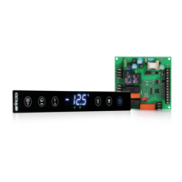
Overview of the c-pro 3 nano CHILL programmable controllers for chillers/heat pumps.
Illustrates the system layout for a dual-circuit air/water chiller.
Presents measurements for control modules and remote interfaces.
Panel fitting measurements for the c-pro 3 nano CHILL control module.
DIN rail mounting measurements for the c-pro 3 EXP micro+ control module.
Models for panel mounting measurements of the EPJgraph remote interface.
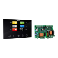
Measurements for fitting the Vgraph remote user interface to a panel.
DIN rail mounting measurements for the EVDRIVE03 module.
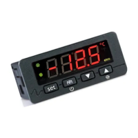
Describes the display and key functions of the controller interfaces.
Details the display and key layout for the c-pro 3 nano+ controller.
Explains the keypad layout and functionality of the Vgraph remote interface.
Explains the password system for accessing different menu levels and functions.
Describes the display when the unit is switched off, including the reason for shutdown.
Shows the main screen display when the unit is operational, including temperatures.
Details system modes and their corresponding displays within the Stat menu.
Explains the meaning of various LEDs and their operational states.
| Brand | Evco |
|---|---|
| Model | EPN2LXP |
| Category | Controller |
| Language | English |