EVCO S.p.A.
c-pro 3 nano CHILL | Application manual ver. 3.0 | Code 144CP3NCE304
page 5 of 96
8.22.8 Setpoint variation from digital input ........................................................................................ 76
8.23 Management of the EVDRIVE03 built into the system ............................................................................ 77
8.23.1 Enablement of EEV Operation ................................................................................................. 77
8.23.2 PID Parameter Settings ......................................................................................................... 77
8.23.3 Modulation of the SH set ....................................................................................................... 77
8.23.4 CAN Configuration ................................................................................................................ 77
8.24 Manual Operation .............................................................................................................................. 78
8.24.1 Compressors ........................................................................................................................ 78
8.24.2 Fans ................................................................................................................................... 78
8.24.3 Pumps................................................................................................................................. 78
8.25 Restoring the Preset Parameters ......................................................................................................... 79
8.26 Parametrisation Pen drive .................................................................................................................. 79
9 ELECTRICAL DIAGRAM ........................................................................................................................... 81
9.1 Layout c-pro 3 nano+ connection ........................................................................................................ 81
9.1.1 Connectors .......................................................................................................................... 81
9.1.2 Connection to the power supply.............................................................................................. 81
9.1.3 Analogue input connection ..................................................................................................... 81
9.1.4 Digital input connection ......................................................................................................... 82
9.1.5 Analogue output connection ................................................................................................... 82
9.1.6 Digital output connection ....................................................................................................... 82
9.1.7 INTRABUS port connection..................................................................................................... 83
9.1.8 RS-485 MODBUS port connection ........................................................................................... 83
9.1.9 CAN port connection ............................................................................................................. 84
9.1.10 USB port connection to a personal computer ............................................................................ 84
9.1.11 USB flash drive connection .................................................................................................... 85
9.1.12 Fitting the termination resistor for the RS-485 MODBUS and CAN networks ................................. 85
9.2 Layout c-pro 3 EXP micro+ connection ................................................................................................. 86
9.3 EVDRIVE03 Connection Layout ........................................................................................................... 87
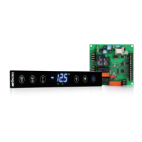
9.4 EPJgraph connection Layout ............................................................................................................... 87
9.4.1 Models for panel mounting ..................................................................................................... 87
9.4.2 Electrical connection with independent power supply ................................................................. 88
9.4.3 Models for wall mounting ....................................................................................................... 88
9.4.4 Electrical connection ............................................................................................................. 89
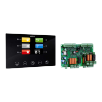
9.5 Vgraph Connection Layout ................................................................................................................. 89
10 DIAGNOSTICS ...................................................................................................................................... 90
10.1 Manual and Automatic Alarms............................................................................................................. 90
10.2 Manual Reset Alarms ......................................................................................................................... 90
10.3 Automatic Reset Alarms ..................................................................................................................... 90
10.4 Alarm Table ...................................................................................................................................... 91
10.5 Alarm History ................................................................................................................................... 94