11
A
B
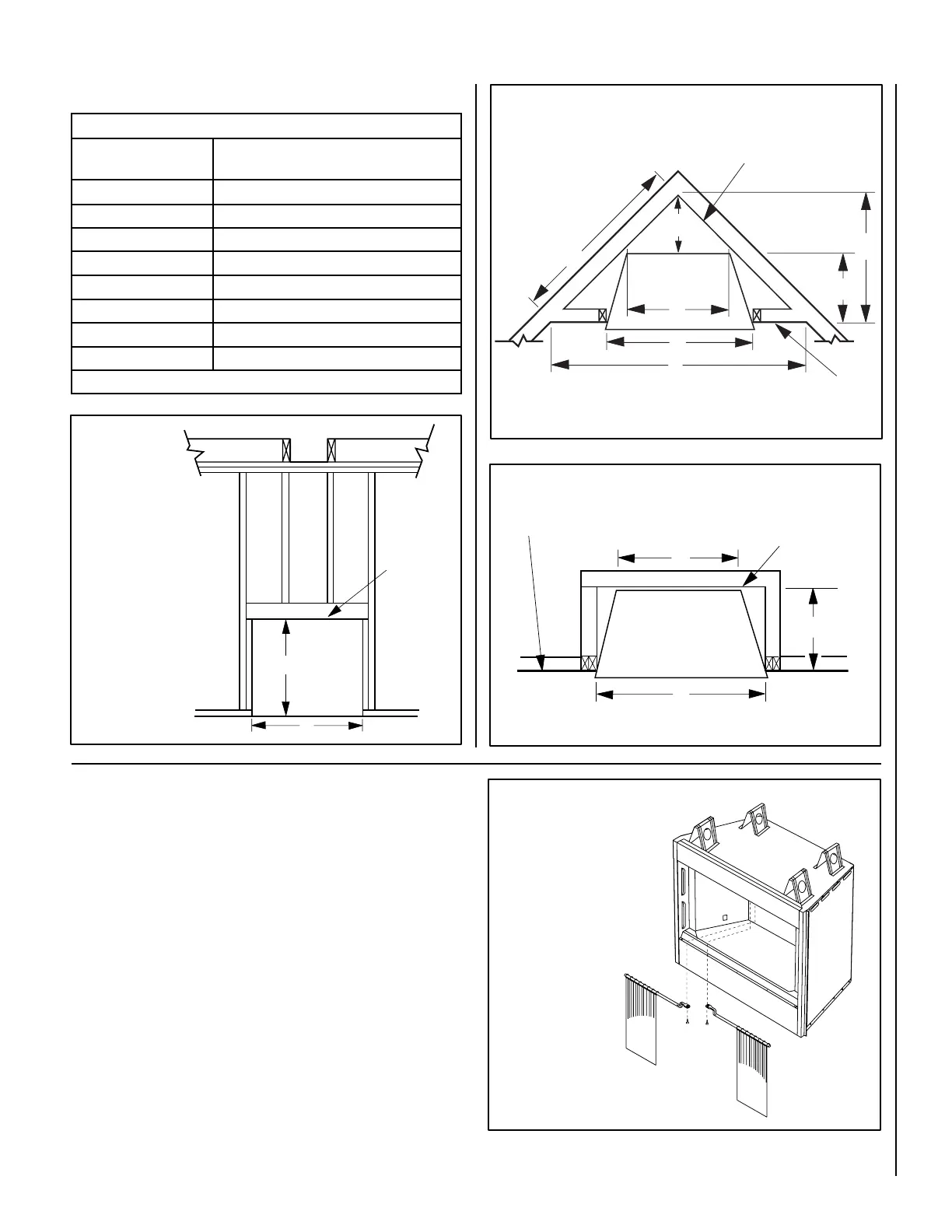
FRAMING SPECIFICATIONS
Figure 7
HoodKitInstallation
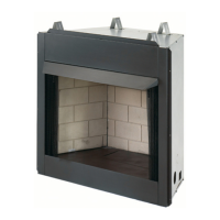
The firebox canopy (hood) must not be modified or replaced with
a canopy that may be provided with the unvented decorative
room heater.
NOTE: A hood comes standard and is required for model EWVF36. The
factory-supplied hood must be installed on the firebox for safe opera-
tion for model EWVF36 in all installations. See
Figure 11.
appearance to your appliance, the hood reduces heat effects to decora-
Figure 4 on Page 7).
Please read this entire manual and understood thoroughly before proceed-
ing with the installation of these kits.
Step 1.
assemblies as shown in Figure 10.
Step 2. Align the hood with the holes in the side frames as shown in
Figure 11. Install three screws as shown in Figure 11
sure hood is level and secure.
Step 3. Reinstall screen and rod assemblies (see Figure 10).
Framing Dimensions
Opening EWVF36
A 42-1/4" (1073)
B 40-1/4" (1022)
C
D
E
F 31-3/4" (807)
G 20-1/2"( 521)
Table 1 -
This Table corresponds to Figures 7, 8 and 9
A
C
D
H
F
G
E
Rough Framing Face
(Unfinished Shown)
Back Wall Of Chase/Enclosure
Including Finishing Materials If Any
Back Wall Of Chase/Enclosure
Including Finishing Materials If Any
Rough Framing Face
(Unfinished Shown)
Corner Installation
A
C
G
Parallel Installation
Figure 8
Figure 9
This Figure corresponds to Table 1
This Figure corresponds
to Table 1
This Figure corresponds
to Table 1
Header
Figure 10
Removing Screens and Rods:
Remove screws (see dotted
lines). Pull out rods from
opening.
Reinstalling Screens and Rods:
Insert rods into corresponding
opening, then reinstall screws
as shown.
WARNING: Do not fill spaces
around the firebox with
insulation or other materials.