- 9 -
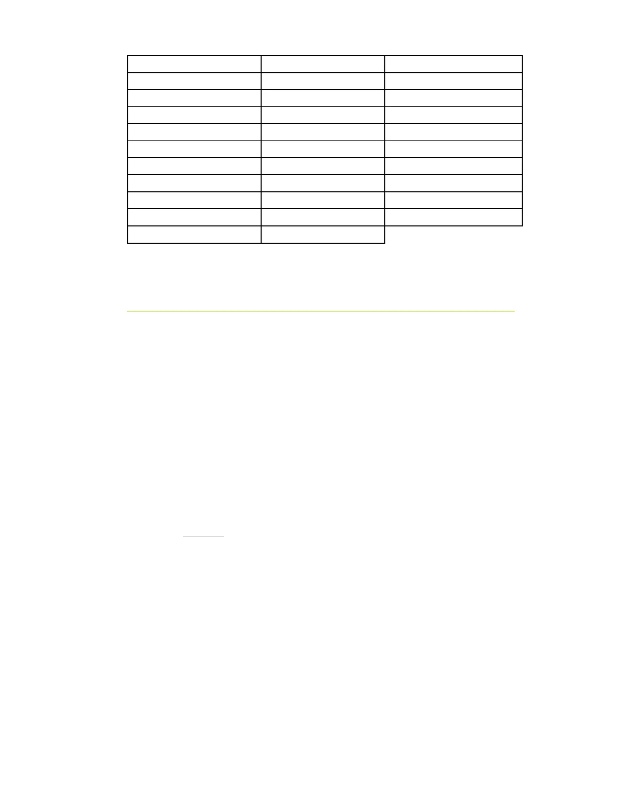
1. CPU Socket 2011-3 12. CMOS Battery 23. EVGauge
2. Intel X99 Southbridge 13. USB 3.0 Headers 24. Thunderbolt GPIO Connector
3. CPU Fan Header (1 amp PWM) 14. USB 2.0 Headers 25. Back Panel Connectors (Figure 2)
4. DDR4 Memory DIMM Slots 1-8 15. CMOS Reset Button 26. 8 pin EPS Connector
5. 24-pin ATX power connector 16. Power Button 27. Supplemental PCI-E 6pin Power
6. Fan Headers (1 amp DC) 17. Reset Button 28. S/PDIF Out
7. PCI-E Disable Dipswitches 18. PC Speaker 29. Probe It Header
8. Intel Sata 6G RAID Ports 19. PCI-E Slot 16x/8x 30. BIOS Selector Switch
9. Intel Sata 6G AHCI Ports 20. PCI-E Slot 8x 31. Removable BIOS Chip
10. Front Panel Connectors 21. PCI-E Slot 4x
11. Debug LED / CPU Temp Monitor 22. Front Panel Audio Connector
PCI-E Slot Breakdown
PCI-E Lane Distribution (40 Lane Processor)
PE1 – x16 (x8 if PE2 is used)
PE2 – x8
PE3 – x8
PE4 – x16 (x8 if PE3 is used)
PE5 – x4 (Gen 2 only, 4 lanes pulled from PCH)
PE6 – x8
PCI-E Lane Distribution (28 Lane Processor)
PE1 – x16 (x8 if PE2)
PE2 – x8
PE3 – x8 (Not functional with a 28 lane processor.)
PE4 – x8
PE5 – x4 (Gen 2 only, 4 lanes pulled from PCH)
PE6 – x4