269
MIDSECTION
TILLER HANDLE SERVICE – LONG HANDLE
12
Route shift and throttle cables and electrical har-
ness through grommet in lower motor cover. Con-
nect harness to engine wiring harness.
Use tie strap to secure harness to throttle body
bracket.
Control Cable Installation
IMPORTANT: DO NOT complete final attach-
ment of cables to shift and throttle levers until all
cables, wires, and hoses have been routed and
grommet has been placed into the lower engine
cover.
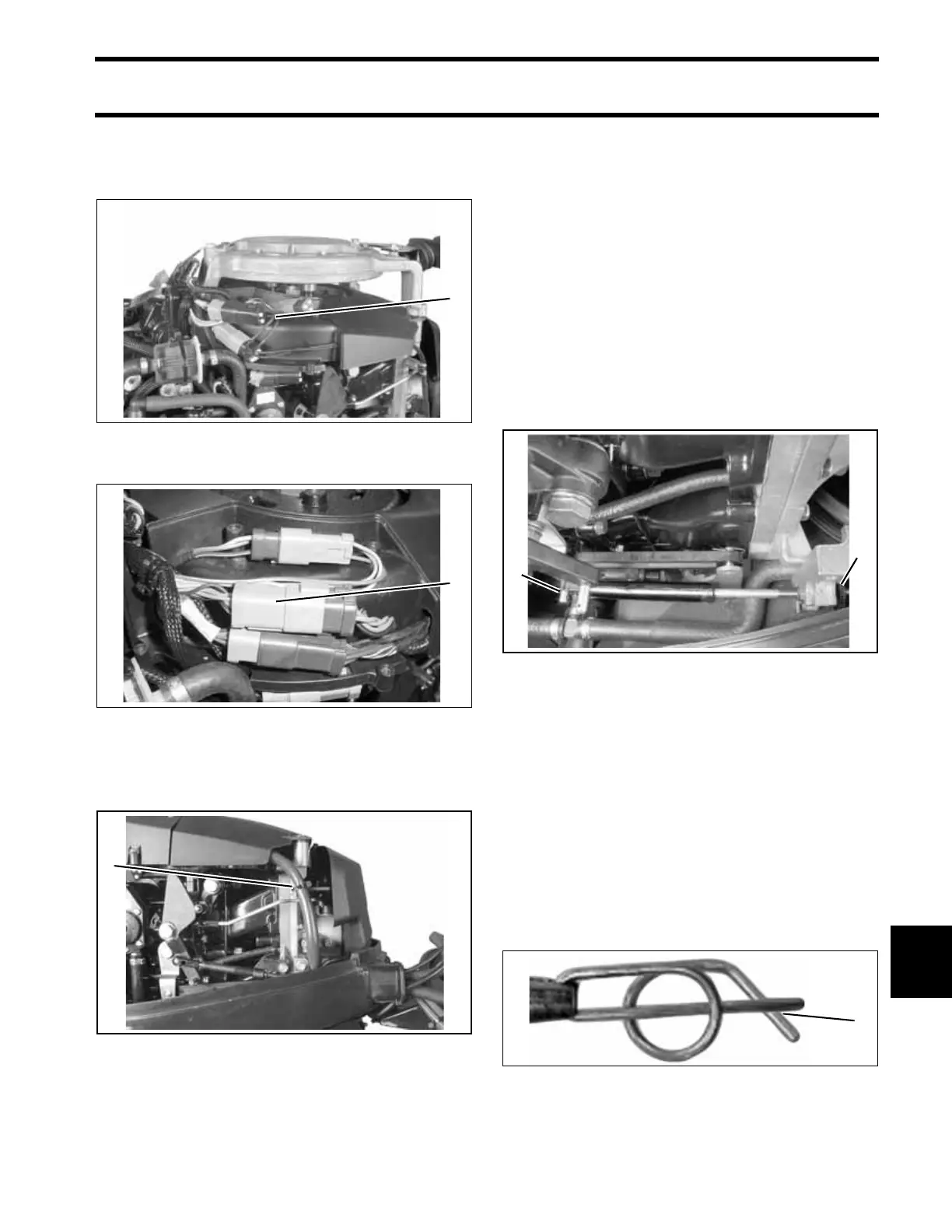
Shift Cable Adjustment
Pull firmly on shift cable casing to remove back-
lash. With outboard and tiller handle shift lever in
NEUTRAL, place the cable trunnion into the lower
anchor pocket. Adjust the trunnion nut so the cas-
ing fits onto the shift lever pin.
Secure shift cable to the shift lever pin. For proper
installation, review the following steps:
• Place washer on pin.
• Position retainer clip with straight section on the
bottom and angled section on the top.
• Use long nose pliers to insert straight section of
clip into linkage pin hole.
• Push the clip towards the hole while lifting on
the curved end with the pliers.
• Be sure retainer clip fully engages the pin.
• Lock the retainer by moving the angled section
behind the straight section.
Rope Start models
1. Electrical harness connector
002511
Tiller Electric models
1. Electrical harness connectors
001999
1. Bracket 006314
1
1
1
1. Shift lever pin
2. Trunnion nut
002100
Locked Retainer Clip
1. Angled section behind straight section
DP0817a
2
1
1