15
www.evolutionpowertools.com
EN
DE
FR
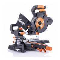
CUTTING REACH & CAPACITY
By using dierent length blades and/or altering the service
position of the workpiece contact plate, it is possible to increase or
decrease the overall ‘reach’ and cutting capacity of the machine.
To adjust the position of the workpiece contact plate:
• Loosenthetwosocketheadedscrews(Fig. 3)
Note: A hex key for these socket headed screws is provided.
The dedicated storage holder for this hex key is located on the
main power cable where it enters the ‘D’ handle.
Always return this hex key to its dedicated storage position
once adjustment has been completed.
• Slidetheworkpiececontactplateinoroutasrequired.
• Securelytightenthesocketheadedscrews.
• Checkthesettingofthemachinebeforebeginning
cutting operations.
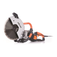
THE TRIGGER SWITCH
The ON/OFF trigger switch is ergonomically located within
the machines main rear ‘D’ handle. (Fig. 4). It is a non-latching
type switch.
• Squeezethetriggerswitchtostartthemachinesmotor.
• Releasethetriggerswitchtostopthemachinesmotor.
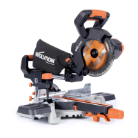
THE STROKE RATE CONTROL DIAL
The stroke rate of the machine can be varied. A stroke rate
control dial is located on the LH (left hand) side of the ‘D’
handle. (Fig. 5).
Note: The ergonomic positioning of this control dial just above
the trigger switch, allows a skilled operator to adjust the stroke
rate of the machine during cutting operations.
Rotating this dial will alter the stroke rate of the machine from
approximately 800 strokes a minute up to a maximum of 2400
strokes per minute.
Note: We recommend that the operator begins any cutting
operation using a slow stroke rate, and increases the stroke rate
to achieve optimum performance as cutting progresses.
Fig. 4
Fig. 5
Fig. 3