18
www.evolutionpowertools.com
LASER ADJUSTMENT FOR
NORTH AMERICAN PLUG MODELS
WARNING:
At no time during this procedure should the
motor be started.
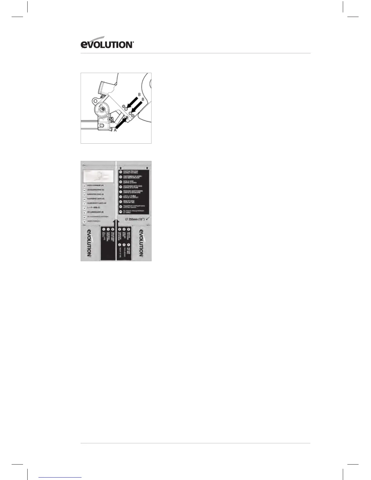
The Laser Module is held in a ‘mounting block’, The ‘mounting
block, itself is located within the machine on two (2) sprung
loaded socket headed screws.
By loosening the cross headed screw (Fig. 8a) slightly, the Laser
Module can be rotated slightly within the “mounting block’. This
will enable the operator ensure that the projected laser line is
set at the vertical.
The two (2) socket headed screws (Fig. 8b) should be viewed
and be adjusted as a pair. They enable the projected laser line
to be aligned exactly with the path of the blade as it enters the
machines table.
To check Laser alignment:
• Placethecardboardlaserjig(Fig. 8c) onto the rotary table.
• LowertheCuttingHeadandtracethepathoftheblade
across the cardboard jig by sliding the Cutting Head forward
and backwards.
• Positionthecardboardsothatthe‘PathoftheBlade’asmarked
on the jig exactly matches the actual path of the blade.
• Fixthecardboardjiginpositionbyusingmaskingtapeorsimilar.
Turn on the Laser.
• Iftheprojectedlaserlineexactlymatchesthe‘Pathofthe
Blade’ both across the table and also in the vertical axis, no
further action is required.
Projected laser line not vertical:
• Loosenthecross-headscrewandgentlyrotatethelaser
module within its mounting block until the laser line is vertical.
• Retightenthescrewandrecheck.
Projected laser line not aligned with
the ‘Path of the Blade’ across the table:
• Adjustthetwosocketheadscrewsalternatelybyno
more than a ¼ of a turn in either direction, observing the
movement of the projected laser line.
• Whentheprojectedlaserlinematchesthe‘PathoftheBlade’
adjustment has been achieved.
Fig. 8a + 8b
Fig. 8c
 Loading...