Maintenance
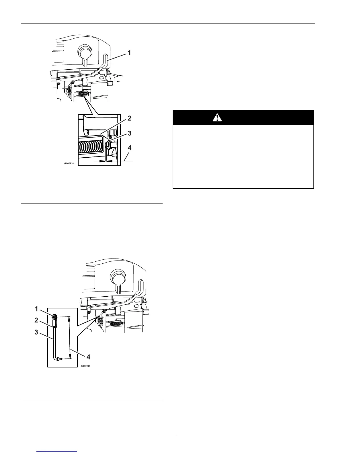
Figure12
1.Parkbrakeengaged3.Thinnylocnut
2.Yoke
4.1/8inch(3mm)gap
betweennutandyoke.
5.Ifparkbrakedoesnotfullydisengagewhenthe
leverisdisengagedcheckthebrakerodlinkage
assembly.Theassemblyshouldmeasure73/8
inch(18.7cm)fromthecenteroftheballjoint
tothecenterofthelowerendofthelinkagerod
(seeFigure13).
Figure13
1.Balljoint3.Parkbrakelinkagerod
2.Jamnut
4.73/8inch(18.7cm)
6.Ifthelinkagedoesnotmeasure73/8inch
(18.7cm)orstilldoesnotdisengageasdesired,
removetheboltthatsecurestheballjointto
thebrakeleverandloosenthejamnutnextto
theballjoint.Rotatetheballjointinhalf-turns
counterclockwiseuntildesireddisengagementis
obtained.
MotionControlLinkage
Adjustment
WARNING
Enginemustberunninganddrive
wheelsmustbeturningsomotioncontrol
adjustmentcanbeperformed.Contactwith
movingpartsorhotsurfacesmaycause
personalinjury
Keepngers,hands,andclothingclearof
rotatingcomponentsandhotsurfaces.
1.Thisadjustmentmustbemadewiththedrive
wheelsturning.Firstraisetheframeandblockup
sothatdrivewheelscanrotatefreely.
2.Removetheelectricalconnectionfromtheseat
safetyswitch,locateddirectlyinfrontoftheseat
switchassembly.
3.Temporarilyinstallajumperwireacrossthe
terminalsintheconnectorofthemainwiring
harness.
4.Starttheengine.
5.Runtheunitatleast5minuteswiththedrive
leversatfullforwardspeedtobringhydraulic
systemoiluptooperatingtemperature.
6.Toobtaintheneutralposition,adjusttheleftand
rightpumpcontrolrodlinkagesthatconnectthe
steeringcontroltothepumpcontrolarmsuntil
thewheelsstop,orcreepslightlyinreverse.
7.Toadjusteachlinkage,loosenthejamnutnext
theballjointattheupperendofthelinkage
rodassembly.Thenrotatetheassemblyusinga
wrenchtoturnthedoublenutsontheassembly
(seeFigure14).
8.Re-tightenthejamnutagainsttheballjointon
eachside.
32
 Loading...