Operation
ProductOverview
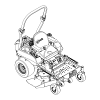
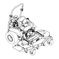
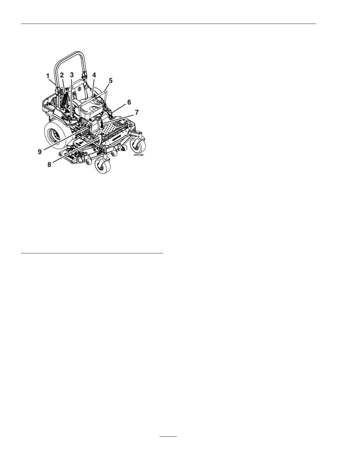
Figure4
1.RolloverProtection
System(ROPS)
6.Fuelcap
2.Rear,shockassembly
(“B1”,“B2”,&“B3”
Modelsonly)
7.Front,shockassembly
(“B1”,“B2”,&“B3”
Modelsonly)
3.EngineControls(right
console)
8.Heightofcutdecklift
pedal
4.Seatbelt
9.Parkingbrakelever
5.Motioncontrollevers
Operation
Note:Determinetheleftandrightsidesofthe
machinefromthenormaloperatingposition.
Controls
MotionControlLevers
Themotioncontrolleverslocatedoneachsideof
theconsolecontroltheforwardandreversemotion
ofthemachine.
Movingtheleversforwardorbackwardturns
thewheelonthesamesideforwardorreverse
respectively.Wheelspeedisproportionaltothe
amounttheleverismoved.
Movingtheleversoutwardfromthecenterposition
intotheT-slotlocksthemintheneutralposition
(Figure5).
Whenthemotioncontrolleversareintheneutral
position,theLCDindicatorappearsinthemessage
displayontheRHconsole(seeFigure9).
26
 Loading...