WARNING
Operatingthemowerwiththebaggerinstalled
andthefrontweightsremovedmaycauseloss
oftractionandsteeringcontroloranunstable
conditionwhichcouldresultininjuryordeath.
•Installthebaggeronlywhenthefront
weightsareinstalled.
•Onlyoperatethemachinewithboththe
baggerattachmentandfrontweights
installed.
Note:Theremovableweightsareheavy.Usecare
whenliftingthem.Makesurethatyoucanholdthe
weightssecurelybeforeliftingthem.Usecaution
whenpositioningyourhandssothatyouDoNotset
themdownonyourhandsorngers.
AssemblingtheTubes
1.Installthelowertubeassembly.
421and501SeriesDecks:
A.Raisethedischargedeector.Slidethemetal
tabonthelowertubeassemblyintotheslot
ofthedeckbracket.Pivotthelowertube
assemblyrearward.Asthelowertubeassembly
openingmountsushwiththedeckmakesure
thesideretaininghook(421seriesdeck)orthe
topretaininghook(501seriesdeck)latches
aroundthedischargedeectorpivotrod(see
Figure12andFigure13).
Figure12
42InchDeck
1.Uppertubepeg
6.Sideretaininghook
2.Rubberretainingstrap7.Deckclasp
3.Uppertube8.Flexiblelatch
4.Dischargedeector
9.Lowertubeassembly
5.Dischargedeectorpivot
rod
10.Metaltab
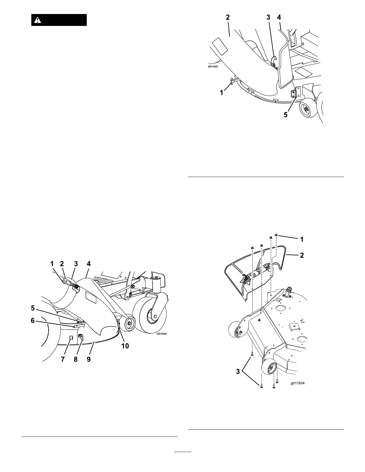
Figure13
50InchDeck
1.Flexiblelatch
4.Dischargedeector
2.Lowertubeassembly5.Metaltab
3.Topretaininghook
B.Securethelowertubeassemblytothedeckby
fasteningtheexiblelatchtothedeckclasp.
502SeriesDecks:
A.Removeandretainthedischargedeectorplate
assemblyanditshardware(see
Figure14).
Figure14
1.Flangenuts
3.Carriagebolts
2.Dischargedeectorplate
assembly
6