Maintenance
VEHICLE(NOTTOTHENEGATIVEPOST)
AWAYFROMTHEBATTERY .STANDBACK.
7.Startthevehicleandremovethecablesinthe
reverseorderofconnection(theengineblock
(black)connectionisthersttodisconnect).
Note:ForSuspensionSeatModelsOnly:Check
thecablesandmakesurethegroundcabledoesnot
rubagainstthetrailingarmorlowershockmountas
showninFigure59.
g236732
Figure59
SuspensionSeatModelsOnly
1.Lowershockmount
3.Groundcable
2.Trailingarm
CheckMowerBlades
ServiceInterval:Beforeeachuseordaily
1.Stopengine,waitforallmovingpartstostop,and
removekey.Engageparkingbrake.
2.Liftdeckandsecureinraisedpositionasstatedin
theCleanGrassBuild-UpUnderDecksection.
3.Inspectbladesandsharpenorreplaceasrequired.
4.Reinstalltheblades(iftheywereremoved)inthe
followingorder:
A.Installeitherthesplinedbushingorblade:
•X-Series:
Installthesplinedbushingthroughthe
bladewiththebushingangeonbottom
(grass)sideofblade.
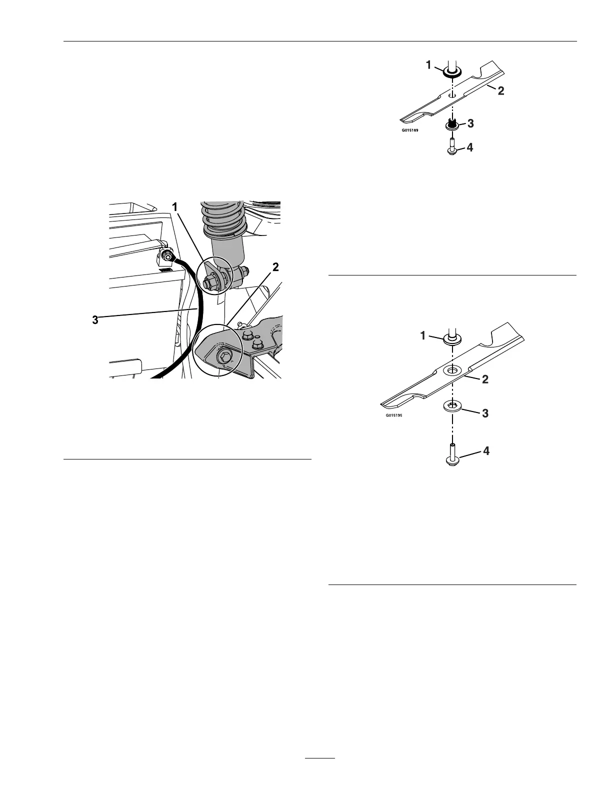
g015189
Figure60
1.Spindle
2.Blade
3.Splinedbushing
4.Bladeboltwasherassembly—T orqueto50-60ft-lb
(68-81N-m)Applylubricanttothreadsasneededto
preventseizing.Copper-basedanti-seizepreferable.
Greaseacceptablesubstitute.
•S-andE-Series:
Installthebladeontothespindleshaft.
g015195
Figure61
1.Spindle
2.Blade
3.Bladedrivewasher
4.Bladeboltwasherassembly—T orqueto50-60ft-lb
(68-81N-m)Applylubricanttothreadsasneededto
preventseizing.Copper-basedanti-seizepreferable.
Greaseacceptablesubstitute.
B.Applylubricanttothethreadsoftheblade
boltasneededtopreventseizing.Copper
basedanti-seizeispreferable.Greaseisan
acceptablesubstitute.
C.Installthesplinedbushing/bladeassembly
andbladeboltwasherassemblyintothe
spindle.Installbladeboltngertight.
D.Placewrenchonthetopspindlenutthen
torquethebladeboltsto50-60ft-lb(68-81
N-m).
57