Maintenance
WARNING
Hotexhaustsystemcomponentsmayignite
gasolinevaporsevenaftertheengineisstopped.
Hotparticlesexhaustedduringengineoperation
mayigniteammablematerials.Firemayresult
inpersonalinjuryorpropertydamage.
DoNotrefuelorrunengineunlesssparkarrester
isinstalled.
1.Stopengine,waitforallmovingpartstostop,and
removekey.Engageparkingbrake.
2.Waitformufertocool.
3.Ifanybreaksinthescreenorweldsareobserved,
replacearrester.
4.Ifpluggingofthescreenisobserved,remove
arresterandshakelooseparticlesoutofthe
arresterandcleanscreenwithawirebrush(soak
insolventifnecessary).Reinstallarresteron
exhaustoutlet.
ThreadLockingAdhesives
Threadlockingadhesivessuchas“Loctite242”,
“Loctite243”,or“Fel-Pro,Pro-LockNutType”are
usedonthefollowingfasteners:
•ROPSspringpinhousing.
•Sheaveandclutchretainingboltintheendof
enginecrankshaft.
•Hydrocrossmembermountingbolts
Threadlockingadhesivesarerequiredforsome
hardwareonengines—seetheEnginemanual.
Copper-BasedAnti-seize
Copper-basedanti-seizeisusedinthefollowing
location:
OnthreadsofBladeBolts.SeeCheckMower
Bladessection.
DielectricGrease
Dielectricgreaseisusedonallbladetypeelectrical
connectionstopreventcorrosionandlossofcontact.
Dielectricgreaseshouldnotbeappliedtosealed
connectors.
Adjustments
Note:DisengagePTO,shutoffengine,waitfor
allmovingpartstostop,engageparkingbrake,and
removekeybeforeservicing,cleaning,ormakingany
adjustmentstotheunit.
DeckLeveling
1.Positionthemoweronaatsurface.
2.Stopengine,waitforallmovingpartstostop,and
removekey.Engageparkingbrake.
3.Checkthetirepressureinthedrivetires.Proper
inationpressurefortiresis13psi(90kPa).
Adjustifnecessary.
4.Positionthetransportlockinthelatching
position.
5.Carefullyrotatethebladesfromsidetoside.
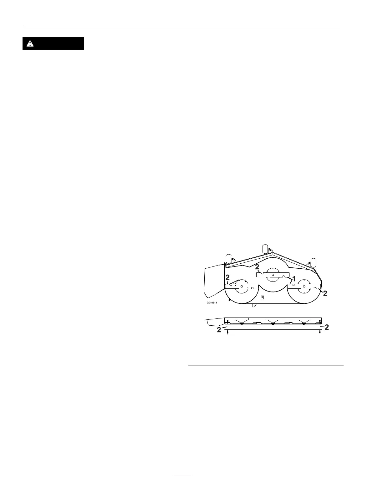
6.Measurebetweentheoutsidecuttingedgesand
theatsurface(Figure68).Ifbothmeasurements
arenotwithin3/16inch(5mm),anadjustmentis
required;continuewiththisprocedure.
g010313
Figure68
1.Bladessidetoside2.Measurehere
7.Setanti-scalprollerstotopholesorremove
completelyforthisadjustment.
8.For60InchDecksOnly:
A.Raisethedecktothetransport(5inch(12.7
cm)cuttingheight)position.
B.Slowlyloosentheadjustingscrewonthe
liftassistspringuntilthescrewcanbe
removed(seeFigure69).Savethescrewfor
reinstallation.
66