Maintenance
Themotioncontrolleverscanbeadjustedhigheror
lowerformaximumoperatorcomfort.
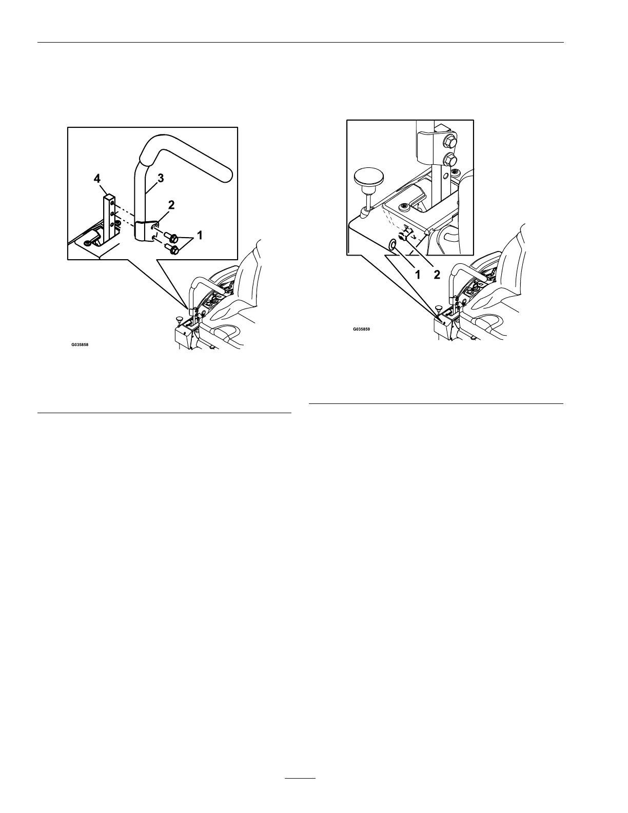
1.Removethehardwareholdingthecontrolleverto
thecontrolarmshaft.
g035858
Figure74
1.Bolts
3.Controllever
2.Slottedhole4.Controlarmshaft
2.Movethecontrollevertothenextsetofholes.
Securetheleverwiththehardware.
3.Repeattheadjustmentfortheoppositecontrol
lever.
AdjustingtheTilt
Themotioncontrolleverscanbetiltedforeoraftfor
maximumoperatorcomfort.
1.Loosentheupperboltholdingthecontrollever
tothecontrolarmshaft.
2.Loosenthelowerboltjustenoughtopivotthe
controlleverforeoraft.Tightenbothboltsto
securethecontrolinthenewposition.
3.Repeattheadjustmentfortheoppositecontrol
lever.
FullForwardTracking
Adjustment
Ifthemachinetravelsorpullstooneside,whenthe
motioncontrolleversareinthefullforwardposition,
adjustthetrackingscrew .
1.Inserta3/16inchhexwrenchthroughtheaccess
holeonthefrontcoverpanel,rotatethetracking
screwclockwiseorcounterclockwisetoadjustthe
travelofthelever.
g035859
Figure75
1.Accessholeonfront
coverpanel
2.Trackingscrew
2.Drivethemachineandcheckthefullforward
tracking.
3.Repeatsteps1and2untildesiredtrackingis
obtained.
MotionControlLinkage
Adjustment
Locatedoneithersideofthemachine,belowtheseat
arethepumpcontrollinkages.Rotatingtheendnut
witha1/2inchdeepsocketwrenchallowsnetuning
adjustmentssothatthemachinedoesnotmovein
neutral.Anyadjustmentsshouldbemadeforneutral
positioningonly.
1.Priortostartingtheengine,pushthedecklift
pedalandremovetheheightofcutpin.Lower
decktotheground.
2.Raisetherearofmachineupandsupportwith
jackstands(orequivalentsupport)justhigh
enoughtoallowdrivewheelstoturnfreely.
3.Removetheelectricalconnectionfromtheseat
safetyswitch,locatedunderthebottomcushion
oftheseat.Theswitchisapartoftheseat
assembly.
70