19
MANUGENEX7xx - Version 2.09
© 2018-2020 EXOR International S.p.A. - Subject to change without notice
5 Connections
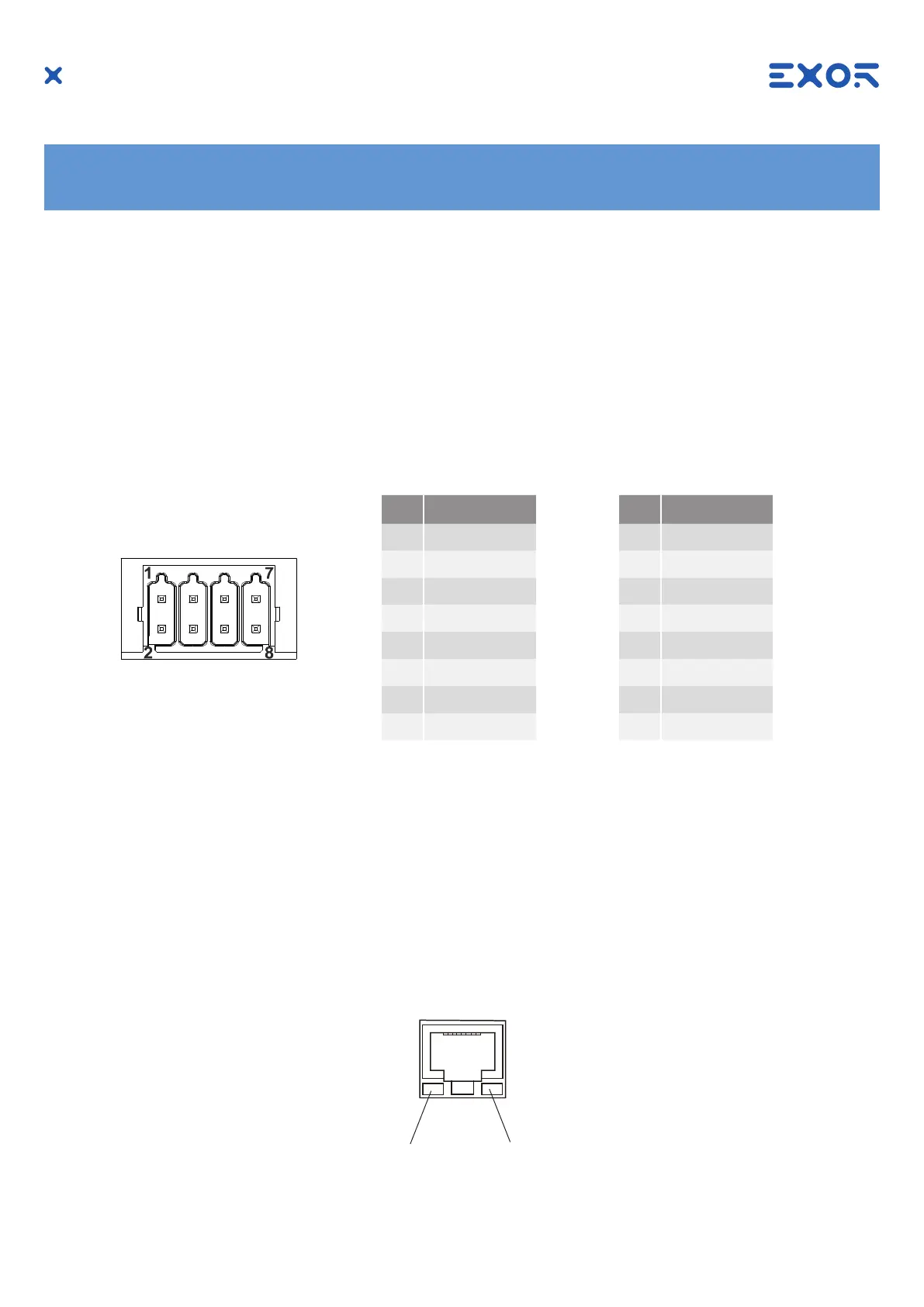
5.1 Serial Port
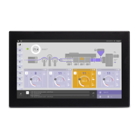
5.2 Ethernet Port
Pin Description
1 CHB-
2 CHA-
3 CHB+
4 CHA+
5 +5V output
6 GND
7
8 SHIELD
The serial port is used to communicate with the PLC or with another type of controller.
Different electrical standards are available for the signals in the PLC port connector: RS-232, RS-422, RS-485.
The serial port is software programmable. Make sure you select the appropriate interface in the programming
software.
The communication cable must be chosen for the type of device being connected.
SERIAL PORT
To operate in RS-485 pins
1-2 and 3-4 must be con-
nected externally.
RS-232 RS-422, RS-485
Pin Description
1 RX
2 TX
3 CTS
4 RTS
5 +5V output
6 GND
7
8 SHIELD
Yellow
OFF: Valid link has NOT been detected
ON: Valid link has been detected
Green
ON: No activity
BLINKING: Activity
The Ethernet port have two status indicators. Please see description in gure.
1 8