Do you have a question about the Extreme Flight RC Extra 260 67 and is the answer not in the manual?
Lists essential components like Transmitter, Receiver, and Lipo Battery needed for the aircraft assembly.
Details necessary adhesives like thin CA glue and threadlocker, plus cleanup materials like acetone.
Unpack all parts, check for any damage, and contact your dealer for assistance if needed.
Attach the landing gear to the fuselage using screws, applying threadlocker to each screw.
Slide the horizontal stabilizer into the fuselage slot, ensuring it is right-side-up and fully engaged.
Apply thin CA glue to the horizontal stabilizer joint, clean up excess, and secure the tail filler piece.
Remove the rear screw holding the tailwheel bracket and swing the tailwheel to the side.
Attach the rudder by sliding the rudder hinge wire in from the bottom.
Re-attach the tailwheel bracket, replace the screw, and add the tiller screw for free movement.
Attach the rudder pushrod to the servo arm and tighten the locking nut.
Attach the elevator pushrod as shown to the elevator servo arm.
Remove the propeller by unscrewing nuts before powering on the aircraft for safety.
Install your receiver and plug in the provided capacitor into any open channel.
Install wings, Lipo battery, and check the airplane's balance by adjusting battery position.
Use an angle-finder app to set recommended control throws and expo values for first flights.
Reinstall the propeller and spinner onto the aircraft.
Use a covering iron or heat gun to shrink wrinkles in the covering before flight.
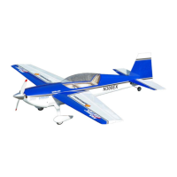
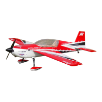
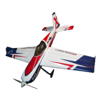
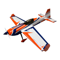
This document serves as an assembly guide for the Extreme Flight RXR (Receiver-Ready) 67" aircraft, a high-quality model designed for hobbyists. The manual emphasizes that this is not a toy and warns of potential serious injury, property destruction, or even death if misused. It stresses the user's responsibility for the safe operation of the assembled aircraft and recommends adherence to the AMA (Academy of Model Aeronautics) safety code or regional equivalent, including joining the AMA for insurance purposes and flying at sanctioned fields. The manufacturer, Extreme Flight RC, provides a 30-day warranty against defects in materials and workmanship from the date of purchase, requiring an original dated receipt for all claims. Support is available via email at info@extremeflightrc.com or phone at 770-887-1794 for US customers.
The Extreme Flight RXR 67" aircraft is a receiver-ready model, meaning it comes largely pre-assembled, requiring the user to install their own transmitter, receiver, and Lipo battery. The aircraft is designed for aerobatic flight, indicated by the control throw recommendations for 3D and XA/Tumbling rates. Its primary function is to provide an advanced remote-controlled flying experience for experienced hobbyists. The "receiver-ready" designation implies that many of the complex internal components, such as servos and the motor, are already installed, simplifying the final assembly process for the user. The aircraft's design, with its large wingspan and control surface throws, suggests it is capable of a wide range of aerobatic maneuvers, from basic to advanced.
The assembly process begins with unboxing and unwrapping all parts, followed by a thorough inspection for any damage. Users are instructed to contact their dealer or Extreme Flight RC directly if assistance is needed or damage is found.
Landing Gear Attachment: The landing gear is attached to the fuselage using screws, with a recommendation to apply a drop of threadlocker (such as Loctite blue #242) to each screw to ensure secure fastening and prevent loosening during operation.
Horizontal Stabilizer Installation: The horizontal stabilizer is carefully slid into its designated slot in the fuselage. Users are advised to take their time, ensuring it is right-side-up and fully engaged. Once properly positioned, thin CA (cyanoacrylate) glue is applied to the joint, both top and bottom, to secure it. Any spilled CA glue should be cleaned immediately with acetone and a paper towel. A tail filler piece is then inserted into the gap in the tail and glued with a few drops of thin CA glue, again cleaning up any spills.
Tailwheel Assembly: The tailwheel bracket is initially swung to the side by removing a rear screw. The rudder is then attached by sliding the rudder hinge wire in from the bottom. After the rudder is in place, the tailwheel bracket is straightened and re-attached, and the tailwheel tiller screw is inserted into the bottom of the rudder. It's crucial to ensure that the tailwheel and rudder move freely together after this step.
Control Surface Linkages: The rudder pushrod is attached to the rudder servo arm, and a locking nut on the back side of the servo arm is tightened to secure it. Similarly, the elevator pushrod is attached as shown in the instructions. These linkages are critical for transmitting control inputs from the servos to the control surfaces.
Propeller Safety: Before powering on the aircraft for programming or service, the propeller must be removed by unscrewing the nuts. This is a critical safety measure to prevent accidental injury from the spinning propeller. The manual explicitly states, "Never power up your aircraft for programming or service until you remove the prop for safety."
Receiver and Capacitor Installation: The user's receiver is installed into the aircraft. A capacitor is provided and should be plugged into any open channel on the receiver. This capacitor offers "ultimate in voltage protection," enhancing the reliability of the electronic system.
Battery Installation and Balance: The Lipo battery is installed, and the aircraft's balance is checked. This is a crucial step for flight stability. The plane should be lifted by the fuselage former immediately behind the wing tube. The Lipo battery is then moved forward or backward until the plane hangs level in this position, achieving the correct center of gravity (CG).
Control Throw Setup: A cell phone with an angle-finder app or a throw gauge is recommended to set the control throws for the elevator, ailerons, and rudder. The manual provides recommended settings for different flight styles:
Propeller and Spinner Reinstallation: After all programming and setup are complete, and safety checks are performed, the propeller and spinner are reinstalled.
The manual highlights one key maintenance aspect related to the aircraft's covering:
The manual strongly advises against treating the model as a toy due to the potential for serious harm. It emphasizes the user's responsibility for the airworthiness of their model and the safe operation of the aircraft. The use of basic hand tools, thin CA glue, and threadlocker (Loctite blue #242) is required for assembly. Acetone and a paper towel are recommended for cleaning up excess CA glue. The aircraft comes with an XT-90 battery connector installed, and users may need adaptors for their specific Lipo battery. The overall tone of the manual is one of caution and responsibility, guiding the user through a detailed assembly process while prioritizing safety.
| Electric Motor | Power 46 or equivalent |
|---|---|
| Material | Balsa and plywood construction |
| Control | 4 channels |
| Servos | 4 high torque servos |
| Wingspan | 67 in (1702mm) |