Hardware Installation
AP-8533 Access Point Installation Guide 14
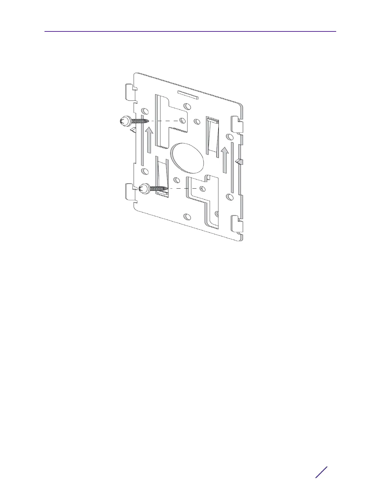
3 At each point, drill a hole in the wall and attach the mounting bracket.
4 Place the Access Point on the mounting bracket.
5 Cable the Access Point using either the Power Injector solution (AP-PSBIAS-2P3-ATR) or
the approved AP-8533 power supply (PWR-BGA48V45W0WW).
For Power Injector installations:
a Connect a RJ-45 CAT5e (or CAT6) Ethernet cable between the Power Injector Data &
Power Out connector and the Access Point’s GE1/POE port.
b Connect a RJ-45 CAT5e (or CAT6) Ethernet cable between the network data supply
(host) and the Power Injector Data In connector.
c Ensure the cable length from the Ethernet source (host) to the Power Injector and
Access Point does not exceed 100 meters (333 ft). The Power Injector has no On/Off
power switch. The Power Injector receives power as soon as AC power is applied.
For standard power adapter (non Power Injector) and line cord installations:
a Connect a RJ-45 Ethernet cable between the network data supply (host) and the
Access Point’s GE1/POE port.
b Verify the power adapter is correctly rated according to the country of operation.
c Connect the power supply line cord to the power adapter.
d Attach the power adapter cable into the power connector on the Access Point.
e Attach the power supply line cord to a power supply.
6 Verify the Access Point is receiving power by observing the LEDs are lit or flashing. For
more information on AP-8533 LED behavior, see LED Indicators on page 19.

 Loading...