3
2. Align the openings of the new faceplate with the buttons and knob and with the LEDs and place the faceplate against the
unit. The magnetic catches fasten the faceplate onto the unit.
TIP: You can wait until the unit is mounted to the junction box or mud ring before placing the new faceplate on the unit.
Replacing button labels
You may wish to customize the button labels. The labels can be changed at any time. Follow these steps to change the button
labels:
1. Remove the faceplate as mentioned in step 1 of Replacing a faceplate.
2. For each button label to be replaced, use the provided Extron
removal tool to gently separate the clear button cap (lens) from
its white diffuser backing as follows: insert the end of the
removal tool into the corner notch and gently twist the tool.
3. Remove the label insert from the transparent button cap.
4. Select one of the button labels from the printed label sheets
included with the MLCPlus. Remove the label from its backing
and remove the clear, protective film from the front of the label.
5. Insert the button label into the button cap. Check for correct
label orientation.
6. Align the cap with the white diffuser and the panel opening, and
press the clear cap into place on the button.
7. Reattach the faceplate to the controller (see step 2 in
“Replacing a faceplate” at the top of this page).
Step 4: Cable All Devices
NOTE: Most examples on the following pages show the MLCPlus100. However, connector wiring and port functions
are identical for all models.
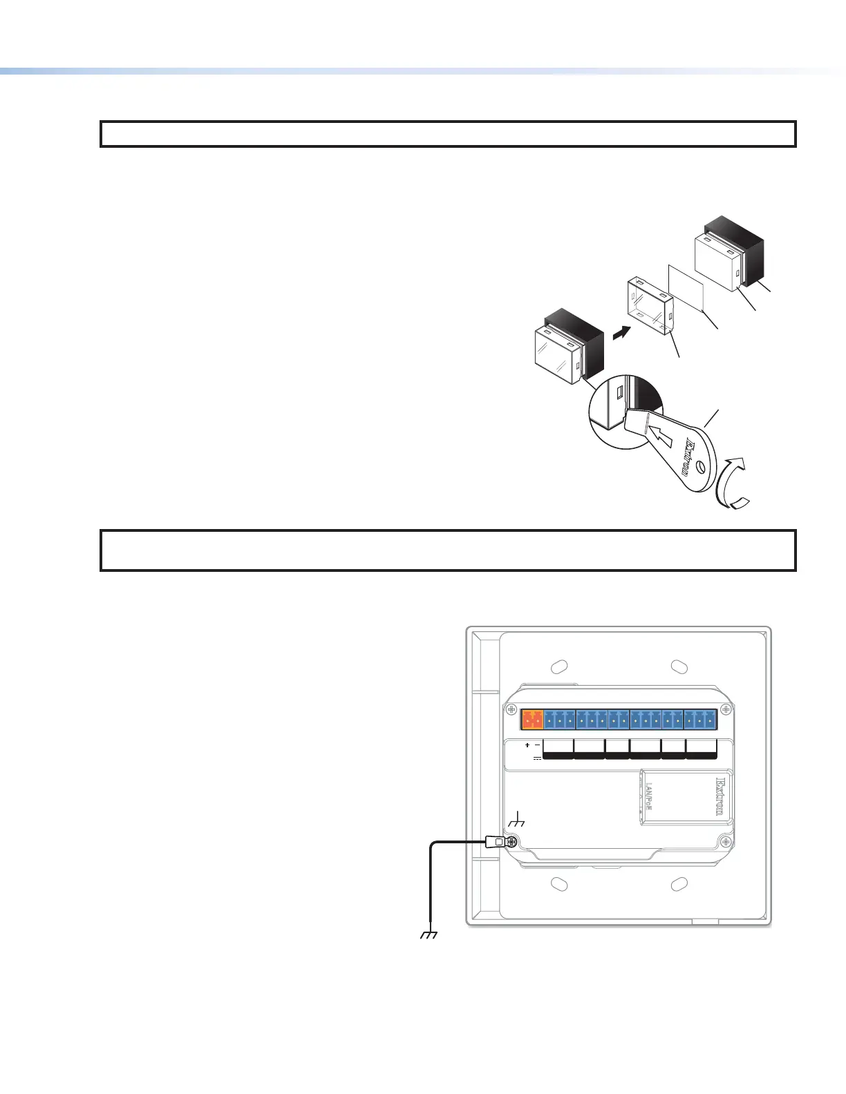
1. If the MLC Plus is not mounted to a grounded metal junction box or a grounded metal equipment rack, Extron recommends
connecting the unit to an earth ground to protect the unit from electrostatic discharge.
To ground the unit:
a. Securely terminate a grounding cable with
a ring terminal.
b. Remove the grounding screw in the
lower left corner of the rear panel, insert
the grounding cable, replace and securely
fasten the screw. Do not over-tighten the
screw. Maximum torque is 2 inch-pounds
(0.2 Newton-meter).
c. Connect the other end of the grounding
cable to an earth ground.
LAN
/
PoE
POWER
12V
0.3A MAX
Tx Rx
G
Tx Rx
2CGCVGS
COM 1 COM 2 VOLIR
GIN
D IN RELAYS
Figure 2. Connecting a Grounding Wire to the MLC Plus
2. Cable devices to the controller (see the following features sections and see Cabling and features on page5).
3. Connect power cords and power on all the devices.
TEXT
Separate the two-
piece button here at
the corner.
y the two
t.
Clear Lens
Removal Tool
2
Diffuser
Insert
button label.
5
Rev. C, 01/24/18:
Added a step to ground the unit.