7
Control — digital input
V
L
GIN
D IN
ELAY
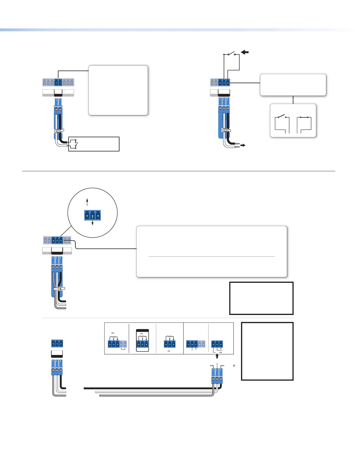
Digital Input
Congure the port with or without
+5 VDC pull-up.
Use this port to:
• Monitor or trigger events and
functions (toggle relays, issue
commands, send e-mail), once
congured.
• Power an LED or other device
that accepts a TTL signal.
nel
Switch, Sensor, LED,
Relay, or Similar Item)
12
C
RELAYS
Rear
Panel
Normally
Open
Common
To Room
Control
Equipment
Closed
Normally
Open
All relays are
normally open.
Relays
• Connect devices for relay control.
• Do not exceed a total of 24V, 1A
for each port.
Control — volume control
GCV
10V 50mA
GCV
REMOTE
10V 50mA
GCV
10V
REMOTE
VOL/MUTE
REMOTE
VOL/MUTE
10V 50mA
G
STANDBY
10V 50mA
GCV
GCV
VOL
IR
IN
GCV
VOL
Ground (Gnd)
Reference voltage input (from amplier) – This allows the MLC Plus to detect when the amp is present.
C
G
Control voltage (variable output to amp from MLC Plus) – This signal controls the amp volume.
V
Ground
C
G
Control voltage
C Plus
Panel
Control voltage output:
0 - 10 VDC
Reference
voltage: ≤10 VDC
NOTE:
Use shielded cable
and place the MLC Plus as
close as possible to the
amplier to avoid picking up
background noise via the
cable.
NOTE: When audio
mute is active, the
MLC Plus sets
control voltage output
to
0 VDC, even if the
voltage range
(minimum and
maximum voltage
limits) have been set
to levels above zero,
such as 2 V to 8 V.
Volume Control
This port can be used to control the volume and mute or unmute the audio for some
Extron audio ampliers with remote volume capability.
• Connect to an Extron audio ampier to
permit volume control via the
MLC
Plus.
• Do not exceed 25 VDC input voltage.
Settings to configure via software:
• Maximum and minimum voltage
limits
• Soft Start mode: off or on (default) − to allow
volume to gradually increase from mute to
the previous level after muting or power-on
to prevent loud audio bursts
Example:
Connecting to
Extron Amplifiers
MLC Plus
Rear Panel
C or
VOL/MUTE
V or 10V G or
MPA 401 Series
MPA 181T,
MP 101 Series
MPA 152MPA 152 PlusXPA 1002
Control — relay