5
I
ADJUST knobs — Rotary controls used with the MENU and NEXT buttons to change settings in conguration
menus (see figure 4 on page 3).
J
I/O display LEDs — A stack of four green LEDs that correspond to the four digital I/O connections on the rear
panel (see figure 1 on page 1). Each LED indicates the on or off status of the corresponding ports. Each port can
be congured as digital input or digital output.
Mode LED Off LED On
Digital input Port input is above the threshold. Port input is below the threshold.
Digital output Port output is off. Port output is on.
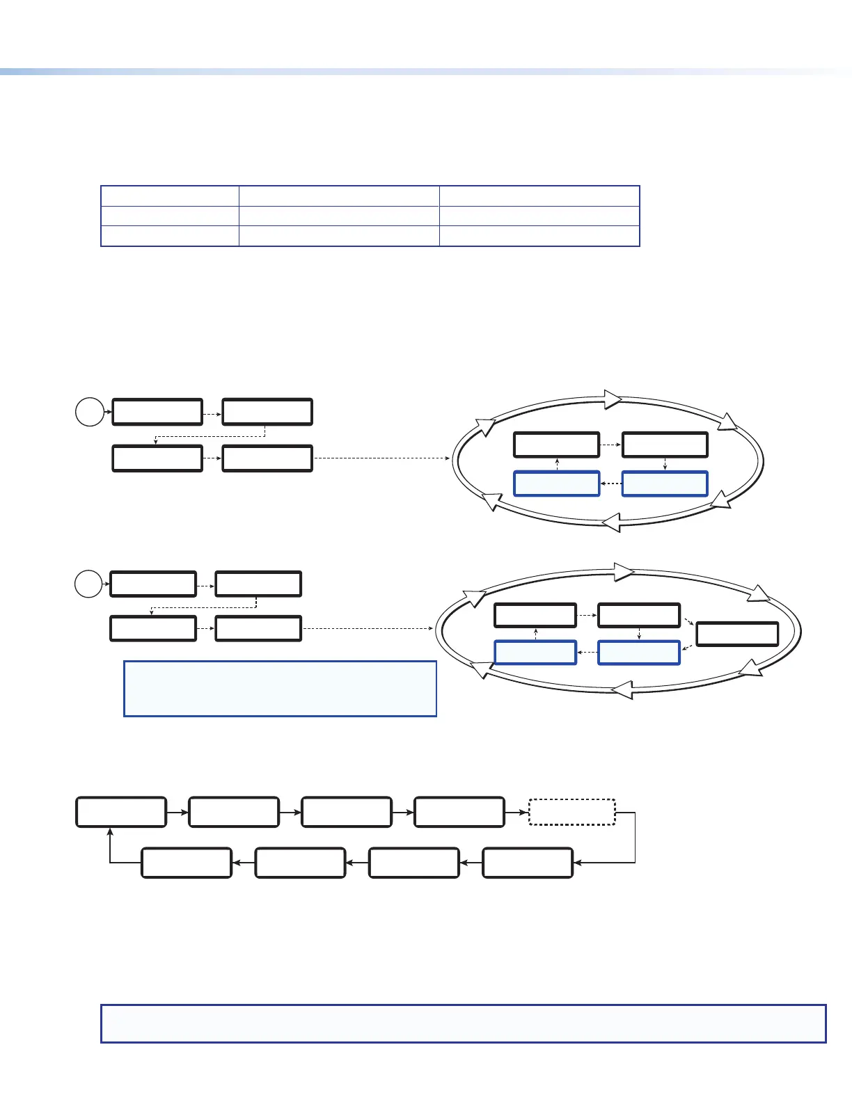
Powering Up
When applying power, the unit undergoes a self-testing sequence (see gure 5 and 6, below). After the testing
sequence is complete (and when the device is not being congured), the default display cycle is shown on the
LCD display (below, right).
The default display cycle shows the selected inputs and their resolutions, stream mode and output resolution.
During recording, two additional items are added to the default cycle with the current length of the recording and
time remaining.
Figure 5. Default Display Cycle for Composite mode
Figure 6. Default Display Cycle for Dual Channel Mode
The SMP 300 Series models contain several primary conguration menus available from the front panel LCD
display. Press MENU to advance through the conguration menus in the order shown below.
(Composite mode only)
PRESETS
PICTURE
CONTROL
RECORD/STREAM
CONFIGURATION
INPUT
CONFIGURATION
BACKGROUND
RECALL
Menu MenuMenu
Menu
ADVANCED
CONFIGURATION
VIEW COMM
SETTINGS
STATUS
EXIT MENU?
PRESS NEXT
Menu MenuMenu Menu Menu
Within each primary menu are submenus with specic conguration options. Stop on a primary menu, then
press NEXT to enter the submenus for the selected conguration.
Use the ADJUST knobs (see figure 4,
I
, on page 3) to change the submenu settings. After selecting new
parameter, press NEXT to enter the new parameter and move to the next submenu, or press MENU to enter the
new parameter and return to the primary menu.
NOTE: The front panel buttons on the SMPmodels can be locked so that configuration using the front panel is
not possible (see “Executive Mode” in the SMP300 Series User Guide).
EXTRON
ELECTRONICS
2
sec.
EXTRON
SMP 35x FW V1.06
45
sec.
SMP 352
INITIALIZING
LOADING
FIRMWARE
30
sec.
~4
sec.
Power
On
NOTES:
• The information shown in the default display cycle differs
depending on the active input and the type of video signal.
• Time Record and Time Remain display only during a recording.
Default Display Cycle
2
sec.
HH:MM:SS
TIME RECORD
2
sec.
2 sec.
In 1 1024x768@60
In 3 720p@60
2 sec.
CHA 5.0 MB
1280x720@30 fps
HH:MM:SS
TIME REMAIN
CHB 5.0 MB
1280x720@30 fps
2 sec.
2 sec.
EXTRON
ELECTRONICS
2
sec.
EXTRON
SMP 35x FW V1.06
45
sec.
SMP 35x
INITIALIZING
LOADING
FIRMWARE
30
sec.
~4
sec.
Power
On
Default Display Cycle
2
sec.
HH:MM:SS
TIME RECORD
2
sec.
2 sec.
In 1 1024x768@60
In 3 720p@60
2 sec.
ARCHIVE 5.0 MB
1280x720@30 fps
HH:MM:SS
TIME REMAIN