16
17
19
2021
18
400 16 732871 - Rev. D
14
17
5 mm
2
1
L
L/2
13
12 Nm
14
20 Nm
13
12 Nm
x2
Translation of the original instructions
ENGLISH
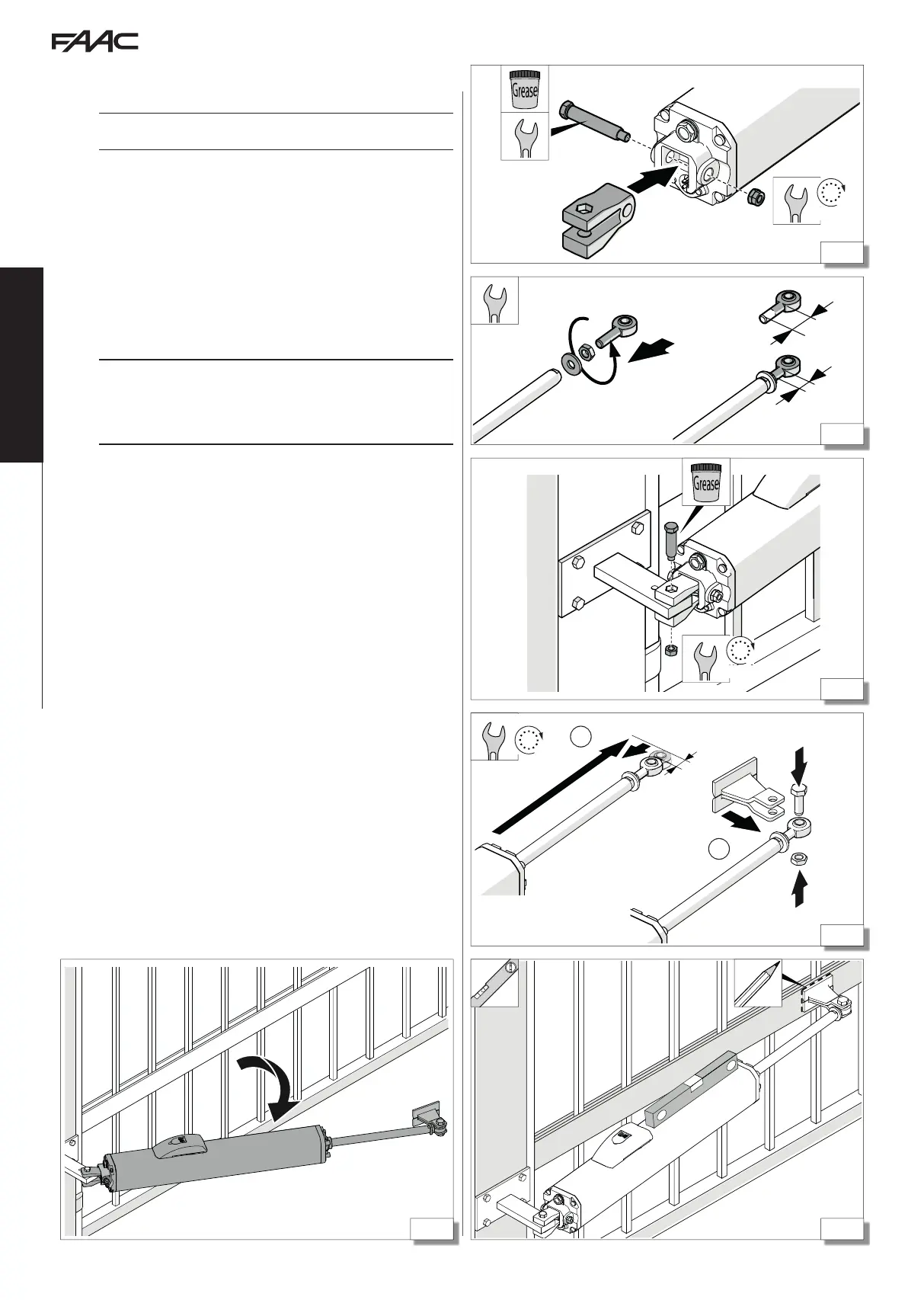
5.3 INSTALLING THE FORK AND JOINT
INSTALLING THE REAR FORK
If you use the SAFEcoder accessory, install the rear fork following the instruc-
tions provided in the specific manual.
1. Grease the long pin.
2. Fasten the rear fork to the actuator using the long pin (16).
3. Tighten the self-locking nut using two hex spanners.
CONNECT THE JOINT TO THE ROD
1. Screw the joint onto the rod, interposing the nut and washer
(17).
2. Adjust the joint to half of its stroke and then tighten the lock nut
(allows for subsequent adjustments).
5.4 INSTALLING THE ACTUATOR
!
The structure of the gate must be suitable for fixing the actuator. If neces-
sary, create a solid support to which to attach it. It is the responsibility of
the installer to provide suitable fastenings for the applied loads. Welding
must be carried out in a workmanlike manner. Safety may be affected if it
is carried out badly.
1. Grease the short pin and use it to connect the rear fork to the rear
bracket (18).
2. Make sure that the actuator has been released. Pull the rod out
completely, as far as it will go, and then push it back in by 5 mm
(19-1).
3. Connect the front bracket to the joint (19-2).
4. With the leaf closed, locate the mounting position for the front
bracket and mark it, making sure that you keep the actuator
horizontal (use a spirit level). Mark the fixing position (20).
5. Rotate the actuator so that it does not obstruct the work area
(21). Then remove the front bracket from the joint.
6. Secure the front bracket to the leaf by welding or using screws.