10
ENGLISH
1
L
OP COM CL CL COM OP
LAMP MOTOR 1 MOTOR 2
J2
J1
+ —
OP — CL NC —
30 Vcc FSW STOP
B — A — + —
FSWTX W.LIGHT LOCK
+ —
J3
230 V
50 Hz
M1
C1
BLU
FSW TX
N
2
3
4
7
6
5
10
9
8
11
12
13 14 15 16 17 18 19 20 21 22 23 24 25 26 27 28
M2
C2
BLU
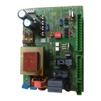
DESCRIPTION AND TECHNICAL SPECIFICATIONS
Table 1: 410 MPS Control unit technical specifications
Power supply 230 V(+6%-10%) - 50 Hz
Absorbed power 10 W
Max. motor load 800 W
Max. accessories load 0,25 A
Temperature range -20 °C +55 °C
Fuses N. 3 (see fig.1)
Operations logics Automatic / Semi-automatic / Safety /
Automatic timer/ Step-by-step semi-automatic
Opening/closing time Adjustable by trimmer (from 0-120 s)
Pause time Adjustable by trimmer (from 0-240 s)
Closing leaf delay time Adjustable by trimmer (from
0 -28 s)
Opening leaf delay time 2.5 s (Can be disabled through bridge)
Thrust force Adjustable by trimmer
Terminal block inputs Open/Stop/Opening safeties/
Closing safeties/ mains power +earth
Terminal block outputs Flashing light - motors
24 Vdc accessories power supply
Quick connector Decoding cards - RP 433 SL/DS
Microswitch programmable functions Operating logics
Closing safeties logics
LAYOUT AND ELECTRICAL WIRING
Fig. 1
Opening
photocells
A
A
A
B
B
Closing photocells
OPEN
TOT.
STOP
For the safety and fail-safe devices, see the “Safety devices”
section.
N.B.: The capacitors are provided with the operators.
Fig. 2
Warning: the max. accessory load is 250 mA. To calculate
absorption values, refer to table 2.
Safety devices
These are all devices (photocells, safety edges, magnetic
coils, etc.) with an N.C. (normally closed) contact which
activate if an obstacle obstructs the area protected by the
a J1 terminal block (fig. 2)
: Earth connection
N. : power supply 230 V~ ( Neutre )
L. : power supply 230 V~ ( Phase)
N.B.: For correct operation the card must be connected to the
system’s earth. Install a suitable differential magneto-thermal
circuit-breaker upstream of the system.
b J2 terminal block (fig. 2)
LAMP.: flashing light output ( 230 V ~)
MOTOR 1 Open /Common/ Close: Motor 1 connection
Can be used in one-leaf application.
(
leaf closing delay)
MOTOR 2 Close /Common/ Open: Motor 2 connection
Not to be used in one-leaf application.
N.B. To check the operation of the equipment at the test
bench, a load must be connected on the MOTOR 1 input.
c J3 terminal block: low voltage (fig. 2) used to connect all
accessories (see table 2).
30 Vdc
– accessories power supply negative
+ accessories power supply positive (+ 30 Vdc)
Caution: Before touching the electronic unit (connections,
programming, maintenance) always switch off the power
supply.
Opening, closing or opening/closing photocells
Fig. 3
a
b
c
d
f
g
h
l
k
j
e
i
NL
J2 J3J1
F1
F4
F2
DL4
DL5
DL3
DL1
DL2
OPENING
LEAF DELAY
DISABLE
FAILSAFE
ON-OFF
m
n
Intelligent Security & Fire Ltd.

 Loading...