9
ENGLISH
ENGLISH
These instructions apply to the following models:
844MPSR ELECTRONIC CONTROL UNIT
1. TECHNICAL CHARACTERISTICS
844 MPSR
Fig. 2
J4J3
J2
CH-DXCH-SX
1 2 3 4 5 6 7 8 9
M
1
2
1
2
3
4
5
J5 J6
J8
J7
230V~ 50Hz
(+6% -10%)
C
35
µ
F
FAACLAMP
MINILAMP
Elettroserratura
Electric lock
Electroserrure
Elektrochloss
Electrocerradura
844MPSR
LN
(L)
FINECORSA
LIMIT SWITCH
FIN DE COURSE
ENDSCHALTER
FIN DE CARRERA
1
2
3
4
5
1
2
Altre sicurezze
Other safeties
Autres sécurités
Andere Sicherheiten
Otros disp. seg.
a
b
2.
ELECTRICAL CONNECTIONS
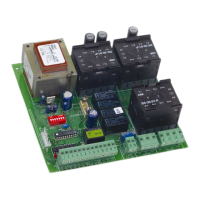
Fig. 1
1. 1. 844MPSR LAY-OUT
P1
RESET
TR1
BRAKE
F2
F1
F3
J7
J8
J6
J5
J4J3
J2
CH-DXCH-SX
J1
DS1
RL1
RL2
IC1
1 2 3 4 5 6 7 8 9
844MPSR
F1F3
P1
TR1
J1
Led
J2 J5 J7
J3
J4
DS1
F2
J6 J8
Ü
Always disconnect the electrical power supply before carrying
out any operations on the control unit (connections, program-
ming, maintenance).
Warning: On disconnecting connector J6, high voltages may be
present on the capacitor output.
Table. 1 TECHNICAL CHARACTERISTICS OF 844MPSR
Power supply 230V~ (+6 -10 %) 50Hz
Motor max. load 650 W
Accessories power supply 24Vdc/24Vac
Accessories max. load 500 mA
Warning light power supply 12Vac (5W max)
Temperature range - 20°C + 55°C
transformer primary
Fuses motor
accessories
for decoding cards or RP receivers
Quick connectors capacitor
limit switch
Inputs OPEN/STOP/CLOSING SAFETY/LIMIT-SWITCH
electric lock
Outputs flashing light
motor
24Vdc/24V~power supply for accessories
pause time (5-10-15-30-60-120-180 sec.)
Logic programming (automatic A1/S1/S2 - semiautomatic E1)
pre-flashing
Motor braking Adjustable by trimmer
Safety timing 255 sec.
Observe points 10, 11, 12, 13 and 14 in the GENERAL SAFETY
INSTRUCTIONS.
Always route the power supply cables separately from the control
and safety cables (keyswitch, receiver, photocells, etc.). Use separate
conduits to avoid any interference.
TAB. 2 844MPSR Control unit components
F1 Fast-acting fuse F1 5x20 F5A/250V (motor )
F2 Time delay fuse F2 5x20 T1.6A/250V (accessories)
F3 Time delay fuse F3 5x20 T250mA/250V (transformer)
P1 RESET button
TR1 Braking adjustment trimmer
DS1 Programming dipswitches
Led Input status indicator LEDs
J1 Quick connector for decoding cards/RP receiver
J2 Low voltage inputs/accessories terminal block
J3 Quick connector for limit switch (LH closure)
J4 Quick connector for limit switch (RH closure)
J5 Motor output terminal block
J6 Quick connector for capacitor
J7 Flasher unit output terminal block (230V
~ max 60W)
J8 Line input terminal block