11
ENGLISH
ENGLISH
Fig. 9
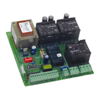
3.7. TERMINAL BLOCK J8 (high voltage)
Terminal block for connection of the 230V~ 50Hz power supply
(L=Line N=Neutral). Connect the earth wire to the operator as
shown in Fig.9
3.8.
INDICATOR LEDS
5 LEDs on the board indicate the status of the terminal inputs
(see Table 3 and Fig. 10):
L
ED
ON
= contact closed
L
ED
OFF
= contact open
TABLE 3 MEANING OF STATUS INDICATOR LEDS
LED ON OFF
OPEN
Command active Command not active
STOP
Command not active Command active
FSW
Safeties disengaged Safeties engaged
FCC
Closing limit disengaged Closing limit engaged
FCA
Opening limit disengaged Opening limit engaged
Fig. 10
J2
1 2 3 4 5 6 7 8 9
(1) With the pre-flashing selected, movement starts after 5 seconds.
(2) If the impulse is sent during pre-flashing, the timer is reset to zero.
LOGIC S1
IMPULSES
GATE STATUS
CLOSED
OPEN
CLOSING
OPENING
STOPPED
OPEN
opens and recloses after
pause time (1)
recloses immediately
(1 and 2)
inverts motion
inverts motion
recloses (1)
STOP
no effect
stops counting
stops
stops
no effect
SAFETY
no effect
recloses after 5 s
from disengagement
inverts motion
no effect
no effect
TABLE 5 LOGIC S1 (SAFETY)
LOGIC S2
IMPULSES
STOP
no effect
stops counting
stops
stops
no effect
GATE STATUS
CLOSED
OPEN
CLOSING
OPENING
STOPPED
OPEN
opens and recloses after
pause time (1)
recloses immediately
(1 and 2)
inverts motion
inverts motion
recloses (1)
SAFETY
no effect
freezes pause until
disengagement
stops and inverts motion
when disengaged (1)
no effect
no effect
TABLE 6 LOGIC S2 (SAFETY PLUS)
TABLE 7 LOGIC E1 (SEMI-AUTOMATIC)
SAFETY
no effect
no effect
inverts motion
no effect
no effect
GATE STATUS
CLOSED
OPEN
CLOSING
OPENING
STOPPED
OPEN
opens (1)
recloses (1)
inverts motion
stops
recloses (reopens when safety
devices are engaged) (1)
STOP
no effect
no effect
stops
stops
no effect
IMPULSES
LOGIC E1
4.
DIPSWITCH SETTINGS
To program the operation of the automation, set the dipswitches
as shown in the diagram above.
Ü Press the RESET button after all programming operations.
Operating logics
There are four operating logics available:
A1 = Automatic S1 = Safety
S2 = Safety Plus E = Semi-automatic
Operation of the different logics is described in tables 4- 5-6-7.
Pause time
The pause time is amount of time the gate remains open
before it re-closes when an automatic control logic is selected.
Pause times include the pre-flashing time, if selected.
Operation of electric lock(s)
Allows you to choose whether the electric lock is to be activated
only before opening or also before closing. In both cases the
lock is released only when the respective limit switch is engaged
(e.g. it is released before opening only if the closure limit switch
is activated).
Pre-flashing
It is possible to select 5 seconds pre-flashing of the flashing light
before any gate movement. This serves to warn any persons in
the vicinity that the gate is about to start moving.
Pre-flashing SW6
Yes ON
No OFF
123456
Operation of electric lock(s)
SW5
Release only before opening (1 electric lock)
ON
OFF
Release before opening and release before
closing (2 electric locks required)
Logic SW1 SW2
E1 ON ON
A1 ON OFF
S2 OFF ON
S1 OFF OFF
Pause time (sec)
Logic
A1 - S2 S1 SW3 SW4
515ONON
10 30 OFF ON
30 60 ON OFF
120 180 OFF OFF
ON
OFF
IMPULSES
LOGIC A1
SAFETY
no effect
freezes pause until
disengagement
inverts motion
no effect
no effect
STOP
no effect
stops counting
stops
stops
no effect
GATE STATUS
CLOSED
OPEN
CLOSING
OPENING
STOPPED
OPEN
opens and recloses after
pause time (1)
recloses after 5 s (2)
inverts motion
no effect
recloses (1)
TABLE 4 LOGIC A1 (AUTOMATIC)
 Loading...