9
844MPS
6
9
8
7
24V~ 5W max
9
8
2A max
MINIDEC
SL/DS
PLUS
844MPS
DECODER
SL/SLP/DS
844MPS
844 T
844 T
844 T
!!
!!
!
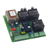
3. DESCRIPTION
3.1. J1 PLUG
The J1 plug is used for rapid connection of cards MINIDEC,
DECODER, RP RECEIVERS (Fig. 3, 4, 5)
Install by fitting the accessory cards so that their components
side faces the inside of the 844 T electronic appliance.
Insert and remove the cards after cutting power.
3.2. TERMINAL BOARD J2 (low voltage)
1 = OPEN A (N.O.) – Total opening
This is any pulse generator with N.O. contact which, when
activated, produces a gate opening movement. In A, E
and S logics, it commands both opening and closing.
To install several Open A devices, connect N.O. contacts
in parallel.
2 = OPEN B (N.O.) – Opening for pedestrians / Closing
This is any pulse generator with N.O. contact which, when
activated in logics A, E and S, produces a gate opening
movement for pedestrians. In B and C logics, it commands
a closing movement.
To install several Open B devices, connect N.O. contacts
in parallel.
3 = STOP command (N.C.)
This is any device (e.g. a push-button) which, by opening
a contact, stops gate movement.
To install several stop devices, connect the N.C. contacts
in series.
!If Stop devices are not connected, link the input to the
common contact (terminal 5) via a jumper.
4 = FSW closing safety devices contact (N.C.)
Safety devices are all devices (photocells, sensitive edges,
magnetic coils) with N.C. contact, which, if there is an
obstacle in the area they protect, operate to interrupt
gate movement. The purpose of the closing safety devices
is to protect the gate movement area during closing.
If the safety devices are tripped during closure, gate
movement is reversed, whereas they have no effect during
opening. If used when the gate is open or pausing, closing
safety devices prevent its closing.
To install several safety devices, connect the N.C. contacts
in series.
!!
!!
! If closing safety devices are not connected, link this
input to the common contact (terminal 5) via a jumper.
5 = Common contact for commands
6 = Negative of accessories power supply
7 = 24 Vdc (+) power supply for accessories
Max load of accessories is 500 mA.
To calculate absorption values, refer to the instructions
for individual accessories.
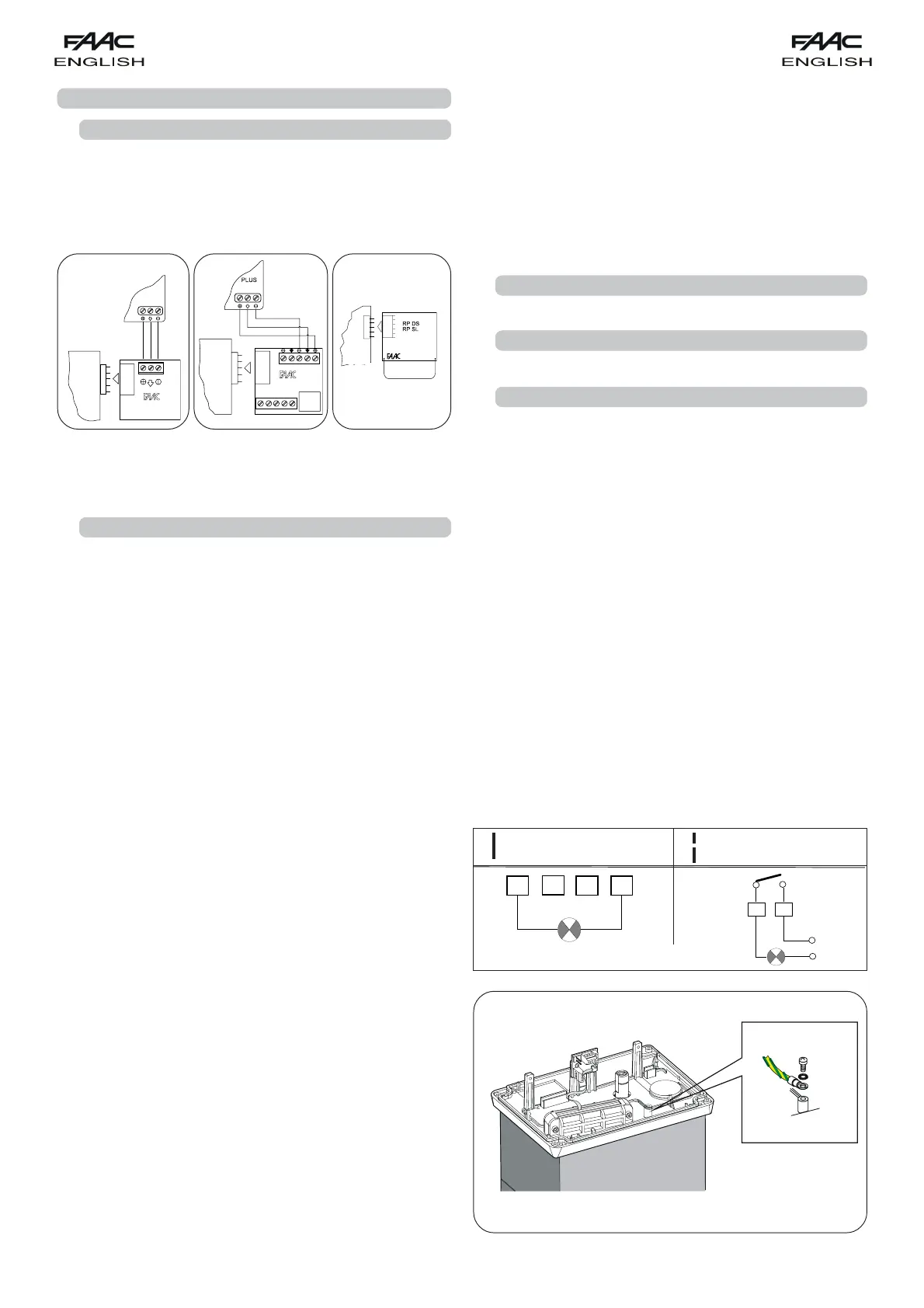
9 = Warning light output (24 Vac)
The maximum load of the warning light is 5 W.
For instructions on operation of the warning light, consult
microswitch programming.
!!
!!
! If you cut out jumper LK1, you obtain a voltage free
contact between terminals 8 and 9 (see Fig. 6).
10 = 24 Vdc (+) power supply for inductive limit switch
11 = Limit switch common contact
12 = Opening limit switch (N.C.)
13 = Closing limit switch (N.C.)
3.3. TERMINAL BOARD J3 (high voltage)
Terminal board for connecting flashlight (max 60W).
3.4. TERMINAL BOARD J4 (high voltage)
Terminal board for connection of motor.
3.5. TERMINAL BOARD J5 (high voltage)
Terminal board for supplying power of 400V 3ph + Neutral - 50 Hz
(see Fig. 1) or 230V 3ph - 50 Hz (see Fig. 8).
Connect the yellow-green earth cable as shown in Fig. 7.
Fig. 6
COMPLETE LK1
INTERRUPTED LK1
(Free contact)
Fig. 7
Fig. 3 Fig. 4 Fig. 5